
Typical requirements
| ATC rotary joint speed | Up to 60 rpm on most models; 15 rpm on a large L-band waveguide unit |
|---|---|
| Rotary joint life (examples) | 20–50 million revolutions (ATC); 100 million (S-band coax example) |
| RF bands (ATC examples) | L-band 1.0–1.4 GHz; S-band 2.7–3.1 GHz |
| RF peak power (examples) | 35 kW (S-band waveguide channel); 110 kW (L-band waveguide channel) |
| Integrated slip ring circuits (ATC examples) | 5–38 ways alongside RF channels |
| Operating temperature (ATC rotary joints) | Typically −40 °C to +60 °C or +75 °C; −55 °C on some models |
| Large-diameter slip ring data | FORJ over 40 Gbit/s aggregate; non-contacting link over 5 Gbit/s |
Machinery we specify motion for
- Air traffic control surveillance radars
- Air defence and surveillance radars
- Naval navigation and surveillance radars
- Weather radars
- Tracking and communication antenna positioners
- Mobile and vehicle-mounted radar masts
- Active array pedestals with coolant feedthroughs
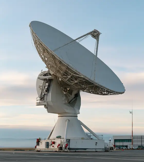
Radar pedestals and antenna positioners turn surveillance, air defence, fire control, air traffic control (ATC), weather and naval navigation radars, as well as tracking and communication antennas. Most rotate continuously in azimuth, around the clock, and many also have an elevation axis. Everything the antenna needs crosses the rotating joint: RF transmit and receive channels, electrical power, control and data, and on active arrays with amplifiers in the antenna, cooling air or liquid. The joint is the part that defines both performance and maintenance life.
Slip rings with RF and waveguide rotary joints
A radar rotating joint is usually one integrated assembly with four elements stacked on a common axis:
- RF rotary joints, coaxial for lower power and broadband channels, waveguide for high-power channels.
- A slip ring for power, control and lower-rate signals.
- A fibre optic rotary joint (FORJ) or contactless data link for high-rate data.
- An encoder and sometimes media feedthroughs for coolant or air.
SPINNER notes that media feedthroughs for air or other coolants are standard in military designs where amplifiers sit in the antenna, and that its ATC range includes a non-contacting six-channel rotary joint covering the S- and L-band primary and secondary surveillance radar frequencies.
Published ATC examples from SPINNER’s catalogue show the spread:
| Example | Channels and bands | RF power | Speed and life |
|---|---|---|---|
| Three-channel S-band | WR284 waveguide, 2.7–2.9 GHz, plus 15–20 slip ring ways | 35 kW peak, 3 kW average (ch 1) | 40 million revolutions |
| Six-channel L/L | WR650 waveguide 1.2–1.4 GHz plus N-type 1.0–1.1 GHz, 38 ways | 110 kW peak, 11 kW average | 15 rpm; 50 million revolutions |
| Nine-channel L-band | 1.0–1.1 and 1.2–1.4 GHz, 35 ways | 5 kW peak | 20 million revolutions |
| Single-channel S-band coax | 2.8–3.4 GHz, 7-16 connector | 50 kW peak | 60 rpm; 100 million revolutions; VSWR 1.06 |
| Waveguide and FORJ hybrid | 8.5–10.5 GHz waveguide plus 12 optical channels | 15 kW (pressurised) | 20 rpm; 10 million revolutions |
Sources: SPINNER ATC rotary joint catalogue and RF rotary joints catalogue. Check channel-by-channel ratings on the current datasheet before relying on them.
On the defence side, Moog’s catalogue lists radar pedestal slip ring capsules and combined slip ring and RF rotary joint assemblies for airborne surveillance radar, and Cobham describes slip rings and RF rotary joints for tracking and surveillance, AESA, fire control, ATC and weather radars carrying power, gigabit Ethernet and video, with FORJ or waveguide options.
What to specify for a radar pedestal slip ring and rotary joint: every RF channel’s band, peak and average power, VSWR, insertion loss, isolation between channels and maximum wow; waveguide size and pressurisation; slip ring circuits; data rates; coolant passages; speed; life in revolutions; and environment. See how to specify a slip ring, the radar and antenna slip ring page, rotary unions and fibre optic rotary joints.
High-speed continuous rotation and large bores
ATC and surveillance radars commonly rotate at a fixed rate, with the SPINNER ATC range rated to 60 rpm on most models. Large antennas and arrays need large bores for cabling and waveguide. Moog’s large-diameter slip rings reach diameters over 1.7 m, power rings up to 1,000 V and 300 A, speeds to 300 rpm, a FORJ option above 40 Gbit/s aggregate, a non-contacting data link above 5 Gbit/s and integrated encoders. See large-diameter slip rings and high-speed slip rings.
Life is set in revolutions, so convert it to calendar time at your duty: 50 million revolutions is just over six years of continuous rotation at 15 rpm, and about 1.6 years at 60 rpm. That is why brush and bearing maintenance intervals, and field replaceability, belong in the specification.
Encoders and position feedback
Radar azimuth encoders report antenna bearing for plotting and must be absolute, robust and accurate for the beamwidth. They are often integrated into the rotary joint assembly. Large-bore capacitive and inductive ring encoders fit around the joint stack: Netzer’s encapsulated DS offers up to 23-bit resolution and accuracy up to 0.006°, and large-bore inductive kits such as the Midi Ultra IncOder are another option. Compare in absolute vs incremental encoders and the encoders hub.
Drives and gearing
Most pedestals use one or more servo motors driving a slewing ring gear through a reduction gearbox, which gives high torque at low speed and holds against wind. Two motors driving the ring in opposition is a common anti-backlash arrangement for tracking axes. Direct-drive frameless torque motors suit smaller, high-precision positioners. Size the drive for:
- Wind load on the antenna at operating and survival wind speeds, including torque from offset centre of pressure.
- Ice load and breakaway torque after freezing.
- Acceleration to speed and any sector-scan reversals.
- Holding with power off: brake or self-locking gearing.
See gearboxes, harmonic vs planetary vs cycloidal, servo drives and motion controllers.
Wind, ice, salt and other environments
- Weather. SPINNER notes ATC joints run 24 hours a day, 365 days a year. Specify temperature (its ATC joints are typically rated −40 °C to +60 °C or +75 °C), humidity, solar load, rain and icing.
- Salt. Naval and coastal radars need sea-water-resistant housings (SPINNER lists them on some models), sealed connectors and corrosion-resistant fasteners. Test to MIL-STD-810H salt fog (Method 509).
- Ice and wind. MIL-STD-810H icing and freezing rain (Method 521) for the pedestal; wind load in the drive sizing.
- Shock and vibration. Mobile air defence radars see transport vibration; shipboard units may need MIL-DTL-901E shock.
- EMC. High-power RF next to servo drives and slip ring signals; MIL-STD-461 or DEF STAN 59-411 applies to the electronics.
- Export control. Military radar components are typically controlled; see the defence and security overview.
Satellite ground stations use closely related pedestals; see satellite antenna motion.
Typical pitfalls
- Specifying VSWR without wow. Rotational variation is what degrades the radar.
- Converting life in revolutions to years incorrectly, or at the wrong rpm.
- Leaving coolant passages out of the first rotary joint specification.
- Ignoring breakaway torque after icing.
- Buying the slip ring and RF joint separately and then discovering they do not stack in the available height.
Send your RF channels, power, speed, life target and environment, and our engineers can propose slip ring, rotary joint, encoder and drive options.
Radar pedestal slip rings and RF rotary joints
A rotating radar usually needs one integrated joint stack: RF rotary joints for the transmit and receive channels, a slip ring for power and control, a fibre optic rotary joint or contactless link for high-rate data, an encoder, and sometimes coolant or air feedthroughs. Specify each RF channel by band, peak and average power, VSWR, insertion loss, isolation and maximum wow, and each data link by rate. Add speed, life in revolutions converted to calendar time at your duty, temperature, sealing and the available stack height. Buying the slip ring and RF joint separately risks finding they do not stack, so specify them as one assembly.
- ATC and surveillance radars: integrated slip ring and RF joint stacks
- Active array pedestals: power, fibre data and coolant passages
- Naval radars: sealed rotating joints
- Tracking antenna positioners: RF channels and Ethernet
- Weather radars: continuous rotation with RF and power
Available through our supply network
All slip rings →Specify slip rings for radar pedestals and antenna positioners →
Encoders for radar azimuth
Radar azimuth encoders report antenna bearing for plotting and must be absolute, accurate for the beamwidth and robust enough to run around the clock for years. Large-bore capacitive and inductive ring encoders fit around the joint stack without a separate geared take-off, which removes a source of error. Specify bore, accuracy after installation, resolution, interface, update rate and temperature range, and check immunity to the high RF fields next to the antenna. Ask whether the encoder can be integrated into the rotary joint assembly by its supplier, and how it is aligned to the antenna boresight. Analogue sine and cosine outputs suit older interpolating electronics.
- Surveillance radars: absolute antenna bearing
- Tracking pedestals: azimuth and elevation feedback
- Naval radars: sealed large-bore encoders
- Joint stacks: encoders integrated with slip rings
Available through our supply network
All encoders and feedback →Specify encoders and feedback for radar pedestals and antenna positioners →
Radar pedestal gearboxes
Most pedestals drive a slewing ring gear through a servo motor and reduction gearbox, which gives high torque at low speed and holds against wind. The gearbox output bearing carries the pinion load, so choose a gearhead rated for high radial force, and use right-angle versions where height is limited. For tracking axes, two motors driving the ring against each other remove backlash. Size for wind torque at operating and survival speeds, acceleration to speed and sector-scan reversals, breakaway after icing, and holding with power off. Specify lubricant low-temperature limit, sealing, corrosion protection for naval and coastal sites, and service life in operating hours.
- Rotating radars: pinion drives on the slewing ring
- Tracking pedestals: dual-motor anti-backlash drives
- Compact positioners: hollow-shaft low-backlash reducers
- Naval radars: sealed gearheads
Available through our supply network
All gearboxes and harmonic drives →Specify gearboxes and harmonic drives for radar pedestals and antenna positioners →
Servo motors for radar pedestal drives
Geared pedestals use brushless servo motors with brakes, sized from the gearbox output torque divided by ratio and efficiency at the required speed. Continuous-rotation radars run for long periods at fixed speed, so check the continuous rating with margin at the highest ambient and solar load, not just peak torque for acceleration. A spring-applied brake must hold the antenna at survival wind with power off. Specify voltage, feedback type, IP rating, shaft seal, connectors and the cold-start torque after icing. Where two motors bias a slew ring, choose identical motors and drives so torque sharing stays predictable across temperature.
- Surveillance radars: continuous-rotation azimuth drives
- Tracking positioners: azimuth and elevation servo motors
- Mobile radars: motors with holding brakes for transport
- Dual-pinion drives: matched motor pairs
Available through our supply network
All servo and stepper motors →Specify servo and stepper motors for radar pedestals and antenna positioners →
Servo drives for radar and positioner axes
Pedestal drives must hold a steady rotation rate for years, or follow a tracking command smoothly, while sharing an enclosure with high-power RF. For dual-motor slew ring drives, the drives or controller need a torque bias or master-follower mode so one motor always holds the gear flank. Specify supply voltage, continuous and peak current for wind gusts and acceleration, feedback interfaces, network, Safe Torque Off for maintenance, and temperature range. Ask how the drive behaves after a supply interruption, so the antenna resumes rotation or stows predictably. Radiated susceptibility matters as much as emissions next to a radar, under MIL-STD-461 or DEF STAN 59-411.
- Rotating radars: constant-speed azimuth drives
- Tracking pedestals: high-bandwidth position control
- Dual-motor drives: torque-biased anti-backlash control
- Mobile radars: rugged drives on vehicle power
Available through our supply network
All servo drives →Specify servo drives for radar pedestals and antenna positioners →
Direct-drive torque motors for precision positioners
Smaller, high-precision positioners and tracking pedestals can use a large-bore direct-drive torque motor in place of a gear train, so there is no backlash or gear wear and tracking is very smooth. The hollow centre passes the slip ring and RF joint stack. The trade-off is holding torque against wind: a direct drive must produce wind torque continuously or rely on a brake, so size it from wind load at operating speed and specify a brake for survival. Choose a version with an encoder designed to resist contamination for outdoor use. Specify bore, outside diameter, continuous torque at ambient, bus voltage and thermal path.
- Precision tracking pedestals: backlash-free azimuth
- Compact antenna positioners: direct-drive elevation
- Test and calibration positioners: smooth rotary axes
- Joint stacks: hollow motors around slip rings and RF joints
Available through our supply network
All frameless and torque motors →Specify frameless and torque motors for radar pedestals and antenna positioners →
Standards to have in view
- MIL-STD-810H (environmental engineering and laboratory tests)
- MIL-STD-461H (control of electromagnetic interference; supersedes MIL-STD-461G)
- MIL-DTL-901E (high-impact shock tests for shipboard equipment)
- DEF STAN 00-35 (environmental handbook for defence materiel)
- DEF STAN 59-411 (electromagnetic compatibility)
- IEC 60529 (IP codes)
Which standards apply depends on the end product and its market. Your engineer will confirm what the component itself needs to meet.