
In short:Optical motion is about tiny, smooth, repeatable moves: lens groups positioned to a micrometre, stages scanning without vibration, telescope axes tracking to fractions of an arcsecond. Choose the motor for smoothness and holding behaviour (micro steppers, voice coils, piezo or ironless direct drive), put the encoder as close to the optic as you can, and budget for Abbe and thermal errors before resolution.
Typical requirements
| Large telescope axis encoder (published example) | Resolution 0.0003 arcsec; system accuracy 0.06 arcsec over 13.2° after compensation |
|---|---|
| 4 m class telescope pointing accuracy (published example) | 0.19 arcsec over 360° azimuth, 0.03 arcsec over 90° elevation |
| Robotic fibre positioners | 500 per focal plane; reconfiguration cut from about 20 to about 3 minutes |
| Micro gearhead for camera and optics drives (example) | 16 mm diameter, ratios 4.4:1 to 4,592:1, up to 0.6 Nm |
| Vacuum-prepared stages (example) | Down to 10⁻⁷ torr, outgassing below 1 × 10⁻⁵ torr·l/s per axis |
| Step resolution, 5-phase stepper | 0.72° full step (500 steps/rev), ±0.036° step accuracy |
Machinery we specify motion for
- Lens focus and zoom drives
- IR and night-vision focus mechanisms
- Microscope and scanning stages
- Surgical microscopes
- Telescope mounts and fibre positioners
- Spectrographs and filter wheels
- Laser processing and beam steering optics
- Laser projection systems
- Machine vision and inspection
- Precision motion stages
What optics and photonics demand from motion
Optical systems move small masses by small amounts, and they notice everything. A lens group that wanders a few micrometres defocuses an image; a stage that vibrates at standstill blurs a scan; a telescope axis that ripples as it tracks smears a long exposure. So motion components here are judged on smoothness, resolution, holding behaviour, heat and vibration, more than on force or speed.
It is a sizeable market. The UK Photonics Leadership Group describes a global photonics market of roughly $1 trillion that has grown by over 6% a year for more than two decades, and puts UK photonics output at £18.5 billion a year. maxon describes the span of optical systems from microscopes to huge space telescopes, plus laser technology, machine vision and sensors.
Where motion components sit in optical systems
| Machine | Motion | Components that matter |
|---|---|---|
| Camera, IR and night-vision lenses | Focus and zoom groups | Micro stepper or coreless DC motor, lead screw or micro gearhead |
| Microscopes and scanning stages | XY scan, Z focus | Linear motors, voice coils, linear steppers, linear encoders |
| Surgical microscopes | Focus head, zoom, positioning arm | Micro steppers, small servo motors, brakes |
| Telescope mounts | Azimuth, elevation, instrument rotation | Direct-drive torque motors, large ring encoders, slip rings or cable wraps |
| Fibre positioners and spectrographs | Many small two-axis robots, filter wheels, slits | Micro steppers, fine gearheads, compact encoders |
| Laser processing and beam steering | Stages and adjustable optics | Linear motors, brushless motors, controllers with position triggering |
| Machine vision and inspection | Camera and part positioning | Servo or stepper axes, rotary stages, encoders |
FAULHABER’s optics applications illustrate the range: DC motors for focus and zoom in night-vision devices, micro steppers in surgical microscope heads, stepper motors in the MOONS spectrograph and in fibre positioning systems for large telescopes, linear motors in a microscope scanning stage, and brushless motors positioning multispot optics for laser soldering and welding.
Focus, zoom and fibre positioning
Most focus and zoom drives are small steppers or coreless DC motors with a fine lead screw or gearhead. maxon’s camera drive example pairs a 16 mm motor running up to 20,000 rpm with a 16 mm gearhead offering ratios from 4.4:1 to 4,592:1 and up to 0.6 Nm. Voice coils, such as the Akribis AVA flat voice coil, give cog-free short strokes for fast autofocus.
Fibre positioning has become a robotics problem. The SDSS-V focal plane systems each deploy 500 robotic fibre positioners on 2.5 m telescopes, cutting field reconfiguration from about 20 minutes with plug plates to about 3 minutes. Each robot carries science and metrology fibres and must avoid its neighbours, so compact, repeatable two-axis drives matter more than speed.
Worked example: specifying a motorised focus axis
A lens group of 20 g must move over 5 mm with 1 µm resolution and hold position with power removed.
- Screw: a 0.5 mm lead screw converts one motor revolution into 500 µm.
- Native step: a 1.8° stepper (200 steps/rev) gives 2.5 µm per full step, too coarse. A 0.72° five-phase stepper such as the Leadshine 5-phase range (500 steps/rev) gives 1 µm per full step.
- Microstepping: microstepping the 1.8° motor by 8 gives a nominal 0.31 µm, but microstep positions vary with load and detent torque, so do not count on it for accuracy without an encoder.
- Holding: a fine-lead screw is usually not back-drivable, so the lens holds position unpowered, which also avoids motor heat near the optic.
- Speed: 5 mm in 0.5 s means 10 rev/s, 5,000 full steps per second on the five-phase motor, which is within reach of small steppers but needs checking on the pull-out torque curve.
If 1 µm must be guaranteed rather than nominal, add a linear encoder on the lens carrier.
Precision stages: accuracy, repeatability and Abbe error
Aerotech separates the terms clearly: resolution is the smallest increment the system can detect or command, repeatability is how closely repeated moves land, and accuracy is closeness to a known standard, verified by laser interferometry to standards such as ISO 230-2. A 1 nm encoder does not make a 1 nm stage.
Abbe error usually dominates. If the scale sits 50 mm from the optical axis and the stage pitches by 10 arcsec (about 48 µrad), the optic moves about 2.4 µm more or less than the scale reads. Mount encoders in line with the work, choose stages with low pitch and yaw, and control temperature, since an aluminium stage grows about 23 µm per metre per degree.
Telescope mounts and direct drive
Large telescopes show what direct drive and modern encoders can do. HEIDENHAIN describes the Gran Telescopio Canarias (10.4 m mirror of 36 segments) with an azimuth scale tape of 48.48 m over about 15 m diameter, giving 0.0003 arcsec resolution and 0.06 arcsec accuracy over 13.2° after compensation. On the 4.3 m Discovery Channel Telescope, stated pointing accuracy is 0.19 arcsec over 360° in azimuth and 0.03 arcsec over 90° in elevation, with the elevation encoders also providing commutation for the motors.
Sidereal tracking is about 15 arcsec per second, so a mount spends most of its life moving very slowly and very smoothly. That favours zero-cogging direct-drive motors such as the Akribis ACD, or curved arc-segment motors like the Akribis ACR built onto a large radius.
Vacuum and cleanroom optics
Photonics, synchrotron and space-optics work often happens in vacuum. Dover Motion prepares stages down to 10⁻⁷ torr with outgassing below 1 × 10⁻⁵ torr·l/s per axis, using vacuum-rated steppers, PTFE-insulated leads, perfluoropolyether lubricant and electroless nickel rather than anodising. Heat is the main limit, so drives cut current when the axis is idle.
In cleanrooms classified to ISO 14644-1, particle generation matters as much as precision. Sealed or bellows-covered stages, cleanroom-grade grease, non-contact encoders and cable carriers chosen for low particle shedding keep optics and wafers clean. Ask suppliers which cleanroom class a stage has been used in, and how it was tested.
Laser systems and beam steering
In laser processing, the stages move the part or the head while the laser fires, so motion quality shows up directly in the cut, weld or mark. Ironless linear motors and direct drives give the smooth velocity needed for consistent energy per millimetre, and controllers that trigger the laser from position rather than time keep spacing even through accelerations. Laser products are classified under IEC 60825-1, so enclosures, interlocks and access doors become part of the motion system’s safety design.
What to send an engineer
- Moving mass, envelope and how the optic is mounted.
- Stroke or angle, and move and settle times.
- Resolution, accuracy and repeatability, and over what travel they apply.
- Holding behaviour required with power off.
- Allowed heat, vibration and stray magnetic field at the optic.
- Environment: cleanroom class, vacuum level, temperature range.
- Feedback and command interface, and production quantities.
Typical pitfalls
- Buying resolution instead of accuracy, then losing it to Abbe and thermal error.
- Trusting microsteps for absolute position without an encoder.
- Putting motor heat next to the optic, causing focus drift as the mount warms.
- Cogging or gear periodic error on slow tracking and scanning axes.
- Anodised parts in vacuum that take days to pump down.
Send us the moving mass, travel, accuracy and environment, and our specialist engineering and supply partners can propose motors, stages, encoders and drives for your optical system.
Micro stepper motors for optics, focus and fibre positioning
Small hybrid steppers move lens groups, filter wheels, slits and fibre positioners in open loop, holding position without power draw at standstill and stepping in known increments. Coreless DC and slotless brushless motors give cog-free, smooth rotation for zoom and fast focusing. Specify frame size, holding and detent torque, step angle (1.8°, 0.9° or 0.72° five-phase), load inertia, lead screw or gearhead, encoder option, heat at the optic and acoustic noise. Microstepping smooths motion, but the accuracy of each microstep is not guaranteed, so use a finer native step or an encoder when position matters.
- Camera and IR lenses: focus and zoom groups
- Spectrographs: filter wheels, slits and gratings
- Telescope fibre positioners: two-axis robot arms
- Surgical microscopes: focus heads
- Laser optics: mirror and beam-expander adjustment
Available through our supply network
All servo and stepper motors →Specify servo and stepper motors for optics, photonics and telescopes →
Linear actuators, voice coils and piezo motors for focus and stages
Linear motion in optics ranges from micrometre focus moves to long, fast scanning strokes. Voice coils give frictionless, cog-free short strokes for autofocus and fast steering. Captive linear steppers make compact focus and slit drives. Ironless linear motors drive scanning stages without cogging, and self-braking piezo motors hold position unpowered, which suits mechanisms that must not drift or heat the optic. Specify stroke, resolution, repeatability, settling time, moving mass, holding behaviour with power off, heat dissipation and vacuum or cleanroom needs.
- Autofocus: fast short-stroke lens moves
- Microscope stages: smooth XY scanning
- Slit and aperture drives: compact linear steps
- Mirror mounts: drift-free fine adjustment
Available through our supply network
All linear actuators →Specify linear actuators for optics, photonics and telescopes →
Direct-drive motors for telescope mounts and rotary optical stages
Direct-drive torque motors remove gears and their backlash, wear and periodic error from rotary optical stages and telescope axes. Ironless designs have zero cogging, so speed stays steady at the very low rates used in tracking and inspection. Curved arc-segment motors can be built onto large radii, such as a telescope azimuth ring. Specify continuous torque at tracking speed, peak torque for slewing and wind loads, cogging and ripple, encoder accuracy, bore, and the heat the motor puts into the instrument.
- Telescope azimuth and elevation: direct drive at sidereal rates
- Rotary inspection stages: smooth low-speed rotation
- Laser and optical turntables: indexing without backlash
Available through our supply network
All frameless and torque motors →Specify frameless and torque motors for optics, photonics and telescopes →
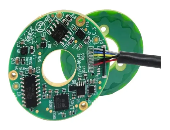
Encoders for telescope mounts and precision stages
In optical positioning the encoder usually limits what the system can achieve, so specify it by accuracy over the travel, not just resolution. Large-diameter rotary encoders on telescope axes reach fractions of an arcsecond after calibration; linear stages need scales mounted close to the line of the optic to avoid Abbe error. Specify resolution, accuracy and repeatability, interpolation, absolute or incremental, interface (BiSS-C, SSI), thermal expansion of the scale, and cleanliness. Absolute encoders avoid homing moves near delicate optics. Ask for the error curve over the full travel, not a single headline figure.
- Telescope mounts: axis angle and velocity
- Microscope stages: linear position
- Rotary optical stages: high-accuracy angle
- Fibre positioner arms: compact absolute angle
Available through our supply network
All encoders and feedback →Specify encoders and feedback for optics, photonics and telescopes →
Low-backlash gearheads for optical positioning
Where a geared drive is acceptable, low-backlash planetary gearheads, flat strain-wave gears and hollow rotary platforms give a compact way to multiply motor torque for mounts, turrets and positioners. Backlash and periodic error show up directly as pointing error, so specify backlash in arcminutes, torsional stiffness, transmission error if available, ratio and noise. Hollow and flat designs leave room for optical paths and cables. Preload the drive against gravity or a spring where reversals would otherwise cross the backlash. Check lubricant suitability for cleanrooms and temperature extremes.
- Camera and sensor turrets: compact reduction
- Optical positioners: zero-backlash strain-wave stages
- Rotary platforms: hollow-shaft reducers for optical paths
Available through our supply network
All gearboxes and harmonic drives →Specify gearboxes and harmonic drives for optics, photonics and telescopes →
Precision drives for optical stages and micro motors
Precision stages need drives with low current noise, fine current resolution and fast loops so the motor does not dither at standstill. Linear motor drives with high-rate pulse or EtherCAT command suit scanning stages; micro servo drives run small brushless and coreless motors; fine microstepping drives smooth stepper focus axes. Specify supply voltage, current, feedback interface, command interface, PWM frequency and noise, and whether the drive can reduce current at standstill to keep heat away from the optics. Keep motor cables away from detector and sensor wiring.
- Scanning stages: linear motor control
- Focus and zoom: micro servo or stepper drives
- Fibre positioners: compact multi-axis drives
Available through our supply network
All servo drives →Specify servo drives for optics, photonics and telescopes →
Slip rings and fibre optic rotary joints for scanners and mounts
Rotating scanners, camera turrets, inspection turntables and some telescope instrument rotators need power, video and data across a continuous rotation. Fibre optic rotary joints carry optical signals directly; HD video slip rings carry camera feeds; pancake rings fit where axial space is short. Specify circuits and current, data and video formats, fibre type and wavelength, insertion loss, speed, bore and the torque the ring adds, since drag matters on smooth low-speed axes. Ask for torque variation over a revolution as well as the mean value, and check the ring's electrical noise near sensitive detectors.
- Rotating scanners: power and data across continuous rotation
- Camera turrets: HD video through the azimuth axis
- Instrument rotators: signals across a field de-rotator
Available through our supply network
All slip rings →Specify slip rings for optics, photonics and telescopes →
Multi-axis motion controllers for optical stages and laser systems
Laser processing, inspection and multi-axis stages need coordinated motion with I/O synchronised to position, for example triggering a camera or laser at set points. EtherCAT controllers run interpolated multi-axis moves, homing and limits, and talk to vision and process systems. Specify axis count, cycle time, interpolation type, position-triggered outputs, communication with the vision or laser controller, and how recipes and coordinate systems are managed across machines. Check how fast position-based triggers fire, because a delay of microseconds becomes a position error at scanning speeds.
- Laser systems: coordinate stages with the laser
- Inspection: camera triggering at positions
- Multi-axis stages: interpolated scanning
Available through our supply network
All controllers and plcs →Specify controllers and plcs for optics, photonics and telescopes →
Standards to have in view
- ISO 230-2 (accuracy and repeatability of positioning of numerically controlled axes)
- IEC 60825-1 (safety of laser products)
- EN 60204-1 (safety of machinery: electrical equipment of machines)
- ISO 14644-1 (cleanrooms: classification of air cleanliness by particle concentration)
Which standards apply depends on the end product and its market. Your engineer will confirm what the component itself needs to meet.
Frequently asked questions
Which motor is best for focus and zoom?
Small hybrid steppers are common because they position in open loop and hold without drawing much power. Coreless DC and brushless motors with encoders give smoother, faster moves, and voice coils suit fast autofocus over short strokes. FAULHABER, for example, lists DC motors for focus and zoom in night-vision devices and micro steppers for surgical microscope focus heads.
Stepper or piezo for fibre positioning?
Both are used. Steppers with fine gearheads give long travel and simple open-loop control; FAULHABER describes stepper motors in fibre positioning systems for large telescopes, and SDSS-V uses 500 robotic fibre positioners per focal plane. Piezo motors give finer steps and hold position with power off, but with shorter travel and different drive electronics. Choose on travel, resolution, holding needs and heat.
How accurate are telescope axis encoders?
On large telescopes, very. HEIDENHAIN describes the Gran Telescopio Canarias azimuth axis measured with a 48.48 m scale tape over about 15 m diameter, giving 0.0003 arcsec resolution and 0.06 arcsec system accuracy over 13.2° after error compensation. Smaller instruments use smaller ring or modular encoders, but the same rule applies: calibrate and compensate systematic errors.
What is Abbe error and why does it matter for optical stages?
Abbe error is the position error caused when the measuring scale is offset from the point you care about and the stage tilts slightly as it moves. The error is the offset times the tilt angle: 10 arcsec of pitch with a 50 mm offset gives about 2.4 µm. Mount the encoder close to the optical axis, or use stages with low angular error, before buying more resolution.
Can motors and stages work in vacuum for photonics?
Yes, with preparation. Dover Motion, for example, prepares stages for high vacuum down to 10⁻⁷ torr, using vacuum-rated steppers with 220 °C magnet wire, PTFE-insulated leads, perfluoropolyether lubricant, electroless nickel instead of anodising, and an 85 °C bake-out. Heat is the main limit, so drives reduce current when the axis is idle.
What should I send for an optics motion enquiry?
Send the moving mass and envelope, stroke or angle, resolution, accuracy and repeatability needed, move and settle times, holding behaviour with power off, allowed heat and vibration at the optic, environment (cleanroom, vacuum, temperature), feedback and interface preferences, and production quantities. A sketch showing where the optic sits relative to the axis helps with Abbe and thermal checks.
Sources
- FAULHABER: Optics and photonics
- SDSS: Focal plane systems
- Thomasnet / HEIDENHAIN: Ultra-precise positioning of the largest telescope in the northern hemisphere
- HEIDENHAIN: Positioning and speed control system for fifth largest telescope in the United States
- maxon: Security systems and optical systems
- Dover Motion: High vacuum positioning tables
- Aerotech: Precision vs accuracy, key differences explained
- UK Photonics Leadership Group: About
Figures are summarised from the sources above and from manufacturers' published data on the date shown. Always confirm against the current datasheet for your exact part.