
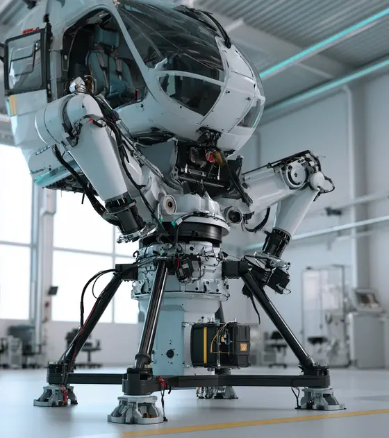
In short:A motion simulator converts vehicle accelerations into short, fast platform moves, so it needs actuators with high velocity, high acceleration and very smooth, quiet motion rather than large stroke. All-electric 6DOF bases now cover payloads from 500 kg to 14,000 kg and Level D flight simulators; size each leg on gravity load plus heave acceleration, and choose control loaders for bandwidth and zero backlash.
Typical requirements
| Electric 6DOF payload (one published range) | 500 kg to 14,000 kg |
|---|---|
| Actuator stroke | 0.30 m (small bases) to about 1.5–1.6 m (full flight simulators) |
| Heave excursion and velocity | ±0.19 m and ±0.5 m/s (500–1,500 kg base) to ±0.9 m and ±0.8 m/s (14,000 kg base) |
| Heave acceleration | About ±0.8 to ±1.0 g |
| Angular velocity and acceleration | ±21–50°/s; ±150–500°/s² |
| Control loader (one published electric unit) | 225 Nm continuous, 560 Nm peak, >100 Hz bandwidth, 4 kHz loop rate, zero backlash |
| Electric actuator speed (manufacturer figure) | Up to 1.5 m/s for roller screw actuators |
Machinery we specify motion for
- Full flight simulators
- Driving and motorsport simulators
- Stewart platforms and hexapods
- G-seats
- Control loading systems
- Vibration platforms
- Military and vehicle training simulators
- VR flight demonstrators
- Continuous-yaw simulator platforms
What a motion simulator asks of its actuators
A motion simulator cannot reproduce sustained acceleration; it can only tilt the occupant and give short, sharp onset cues, then quietly wash the platform back to centre before the next cue. That shapes everything about the motion hardware. Strokes are modest, but velocities, accelerations and smoothness are high, the actuators reverse constantly, and any knock, cogging or noise is felt or heard by the crew. Moog’s simulation range shows the spread of the market: 6DOF motion bases in hydraulic, electric and hybrid forms, plus control loading, G-seats and vibration platforms, for flight training, driver training, vehicle development and entertainment.
Where motion components sit in a simulator
| Machine | Motion | Components that matter |
|---|---|---|
| Full flight simulator | 6DOF base carrying cockpit and visual | Six roller or ball screw servo actuators, absolute encoders, high-bandwidth drives, brakes |
| Driving and motorsport simulator | Fast, short-stroke 6DOF, sometimes on a yaw table or XY rails | Servo actuators, direct-drive yaw motor, slip ring, linear guides |
| Control loading | Force feel on stick, yoke, pedals, collective | Direct-drive or low-cogging servo motor, high-resolution encoder, load cell |
| G-seat | Pressure and tilt cues through the seat | Small servo actuators or motors |
| Vibration platform | High-frequency, small-amplitude cues | Voice coils or short-stroke servo actuators |
| Hexapod | Precise 6DOF positioning | Precision screw actuators, encoders |
| Entertainment simulator | Motion seats and theatres | Electric actuators, show controller, slip rings for rotation |
Motion cueing and why smoothness matters
The cueing algorithm filters the simulated vehicle’s accelerations: high-frequency onset cues go to the platform, sustained acceleration is suggested by tilting the occupant against gravity, and the platform is then returned slowly to neutral below the threshold the occupant can sense. Every one of those phases depends on the actuators following small, smooth commands accurately. Friction steps, screw noise, cogging torque or a drive that hunts around zero velocity are felt as false cues. That is why specification sheets for simulator actuators talk as much about noise, smoothness and frequency response as about force.
Electric 6DOF motion bases: what the numbers look like
Moog’s motion systems brochure gives a clear view of current all-electric bases. Moog states these are minimum capabilities based on software limits.
| Base | Payload | Actuator stroke | Heave | Heave velocity | Heave acceleration | Roll/pitch acceleration |
|---|---|---|---|---|---|---|
| E12 | 500 or 1,500 kg | 0.30 m | ±0.19 m | ±0.5 m/s | ±0.82 g | ±300°/s² |
| E26 | 1,800 kg | 0.66 m | ±0.41 m | ±0.6 m/s | ±1.0 g | ±250°/s² |
| E60 | 14,000 kg | 1.07–1.59 m | ±0.59–0.90 m | ±0.8 m/s | ±0.8 g | ±150°/s² |
Two patterns stand out. Heavier bases trade angular acceleration for payload and stroke, and even full flight simulators stay within about 1 g heave. For full flight simulators, TRU Simulation describes an electric 6DOF system with 60-inch actuators designed to meet Level D tests for linear acceleration, synchronisation, step response and frequency response, and qualified under FAA, EASA, CAAC and CASA.
Why electric? Curtiss-Wright Exlar cites about 90% efficiency for its electric actuators against about 50% for hydraulics, speeds up to 1.5 m/s, and no oil leaks, noise or hydraulic power unit. Treat those as manufacturer figures, but the practical gains in infrastructure and maintenance are why most new bases are electric.
How to size a motion base actuator: worked example
Take a driving simulator with a 1,500 kg payload on a 500 kg moving platform, six legs at about 35° from vertical in the neutral pose, and a target of 0.8 g heave acceleration and 0.5 m/s heave velocity.
- Static load per leg: 2,000 kg × 9.81 = 19.6 kN shared by six legs, divided by cos 35° (0.82): about 4.0 kN each.
- Heave acceleration: at 0.8 g upward, the vertical load is 1.8 times static, so about 7.2 kN per leg.
- Off-centre and combined moves: the centre of gravity is rarely central, and pitch plus heave loads some legs more than others. A margin of 1.5 is a reasonable starting assumption, giving about 11 kN peak per leg. Confirm with a full kinematic and dynamic model.
- Leg velocity: 0.5 m/s heave is about 0.41 m/s along each leg; combined moves push it higher, so design for about 0.6 m/s.
- Screw and motor: with a 25 mm lead, 0.6 m/s needs 1,440 rpm. Peak mechanical power is about 11 kN × 0.6 m/s, or 6.6 kW per leg, though all legs rarely peak together.
- Continuous rating: the legs hold about 4 kN for the whole session, so the motor’s continuous torque must cover the static load with thermal margin, plus the RMS of the cueing profile. A brake or mechanical rest holds the platform when parked.
Compare this with the E12 class above (1,500 kg, ±0.5 m/s, ±0.82 g) as a sanity check. Our linear actuator sizing guide and ball screw vs roller screw cover screw life and selection.
Control loading, G-seats and vibration cues
Control loaders give the controls their feel: centring forces, breakout, trim, stick shaker and the change in force with airspeed. They are torque-controlled servo systems where friction and backlash ruin the result. TRU’s electric control loader is a good benchmark: brushless AC motor, 225 Nm continuous and 560 Nm peak, 750°/s, zero backlash, more than 100 Hz system bandwidth and a 4,000 Hz iteration rate over EtherCAT.
That points to frameless or housed direct-drive torque motors, or low-cogging servo motors with minimal gearing, high-resolution encoders and servo drives with fast current loops. G-seats and vibration platforms use smaller servo actuators to press seat panels or shake the cockpit at higher frequencies than the base can.
Continuous yaw, cables and slip rings
Most 6DOF platforms move through limited angles, so cables run in flexible loops. Driving simulators on yaw tables, rotating pods and some entertainment simulators rotate further or continuously, and then a through-bore slip ring or an Ethernet slip ring carries power, network, video and safety circuits to the cockpit. Read Ethernet through slip rings and our page on slip rings for amusement rides.
Certification and safety
Flight simulation training devices are qualified under EASA CS-FSTD, FAA 14 CFR Part 60 and the ICAO Doc 9625 criteria. TRU notes that most national rules align with either the FAA or EASA framework. Qualification tests the whole device, so the motion system must hold its performance and repeatability over years of training hours. Entertainment simulators that carry the public fall under amusement ride standards such as EN 13814. In both cases, the drives need Safe Torque Off and a defined safe settle to a parked position on power loss or fault.
Typical pitfalls
- Sizing legs on payload alone, without heave acceleration or off-centre loads.
- Ignoring regeneration, so the DC bus trips when the platform drops.
- Choosing gearing with backlash in a control loader or yaw drive, which the occupant feels.
- Homing with people on board because the legs lack absolute feedback.
- Running data through power rings on a yaw slip ring and losing the network.
What to send an engineer
- Simulator type and payload mass, with centre of gravity height and offset.
- Required excursion, velocity and acceleration in each of the six axes, or a reference platform you want to match.
- Base and platform joint geometry, if already fixed.
- Session length and a representative cueing profile for thermal sizing.
- Certification target (for example EASA CS-FSTD level) or ride standard.
- Supply voltage, host computer interface and fieldbus.
- Noise limits and whether continuous yaw or control loading is in scope.
With that, our specialist engineering and supply partners can propose actuators, motors, drives, encoders and slip rings for your platform.
Electric actuators for flight simulator motion bases
Each leg of a 6DOF Stewart platform is a servo actuator that must accelerate quickly, reverse smoothly thousands of times an hour and stay quiet enough not to spoil the illusion. Ball or roller screw rod actuators driven by servo motors have largely replaced hydraulics on new bases. Specify stroke, peak and continuous force per leg, peak velocity and acceleration, the duty profile, end-of-stroke cushioning, brake for parking, and the noise and vibration limits. Roller screws give more load capacity and life for heavy cockpits; ball screws suit lighter driving and entertainment bases.
- Full flight simulators: six legs carrying the cockpit and visual system
- Driving simulators: fast, short-stroke legs for road feel
- Hexapods: precise 6DOF positioning
- Seat movers: small heave and pitch actuators
Available through our supply network
All linear actuators →Specify linear actuators for motion simulation →
Servo motors for control loading, G-seats and motion legs
Servo motors drive the actuator screws on electric motion bases and provide the force feel in control loaders and the pressure cues in G-seats. What matters is low cogging and torque ripple, fast torque response and high-resolution feedback, because pilots and drivers feel small disturbances. Specify continuous and peak torque, speed, rotor inertia against the load, encoder resolution, brake, cooling and acoustic noise. Size the motor on RMS torque over a representative training profile, not only on the peak manoeuvre.
- Motion legs: drive the ball or roller screw
- Control loaders: force feel on stick, yoke and pedals
- G-seats: inflate or press seat panels to cue acceleration
- Vibration platforms: small, high-frequency cues
Available through our supply network
All servo and stepper motors →Specify servo and stepper motors for motion simulation →
Direct-drive motors for control loaders and yaw tables
Direct-drive torque motors remove gearing, so there is no backlash, low friction and a stiff, fast torque loop: exactly what a control loader needs to reproduce stick and pedal forces. Large housed direct-drive motors also turn yaw tables and turntables under driving simulators. Specify continuous and peak torque, speed, cogging, encoder resolution, bore size and bus voltage. Ironless or low-cogging designs feel smoother at the controls, at the cost of lower torque density. Check the thermal rating for long sessions with sustained control forces, such as trimmed-out holding loads.
- Control loaders: direct-drive force feel
- Yaw tables: continuous or large-angle yaw under a cockpit
- Steering wheel force feedback: driving simulators
Available through our supply network
All frameless and torque motors →Specify frameless and torque motors for motion simulation →
High-bandwidth servo drives for motion simulators
Simulator drives need high current-loop and velocity-loop bandwidth, synchronised EtherCAT updates across all six legs and Safe Torque Off for maintenance and emergency stops. Regeneration is significant: when the platform lowers or decelerates, energy flows back into the DC bus, so plan shared bus or braking resistors. Specify supply voltage, continuous and peak current, feedback protocol, fieldbus cycle time, STO and safety ratings, and how the drives bring the platform down safely on power loss. Tuning matters as much as hardware: notch filters and feed-forward help suppress platform resonances.
- 6DOF bases: six synchronised leg drives
- Control loaders: fast torque control
- Platform settle: controlled descent on a fault
Available through our supply network
All servo drives →Specify servo drives for motion simulation →
Encoders for simulator actuators and control loaders
Motion cueing works on leg lengths, so each actuator needs reliable absolute position at power-up to avoid a homing run with a crew on board. Control loaders need high-resolution angle feedback for smooth force feel. Specify absolute or incremental, resolution, interface (BiSS-C, SSI), bore and mounting, and how the encoder copes with vibration. Multi-turn absolute motor encoders are usual on legs; large-bore ring encoders fit direct-drive loaders and yaw tables. Robust capacitive or magnetic linear scales can measure leg length directly where screw wind-up or wear would otherwise creep into the kinematics.
- Motion legs: absolute leg length
- Control loaders: stick or yoke angle
- Yaw tables: large-bore angle feedback
Available through our supply network
All encoders and feedback →Specify encoders and feedback for motion simulation →
Slip rings for simulator yaw tables and rotating platforms
Any simulator that rotates continuously in yaw, such as driving simulators on turntables or rotating training pods, needs a slip ring to carry power, video, network and safety circuits to the cockpit. Specify power circuits and current, Gigabit Ethernet or video channels, safety-circuit routing, speed, bore for cables and hoses, and the vibration from the motion base. Keep data on separate shielded rings and check end-to-end link quality. Ask for the rated life in revolutions, since a yaw table in daily training use builds up rotations quickly, and confirm brush maintenance intervals.
- Driving simulators on yaw tables: power and data to the cockpit
- Rotating training pods: video, intercom and safety circuits
- Entertainment simulators: show control and audio
Available through our supply network
Gearheads for simulator yaw drives and seat movers
Most motion legs use a belt or direct coupling to the screw, but yaw drives, rotating seats and smaller entertainment platforms often use a low-backlash planetary gearhead or a hollow rotary platform reducer. Specify ratio, backlash in arcminutes, output torque including emergency stops, radial and moment load, and noise. Backlash under reversing load is felt as a knock, so choose precision classes for anything the occupant can feel. Check the gearhead's noise level at the operating speed too, because occupants sit close to the drive.
- Yaw drives: motor-to-turntable reduction
- Seat movers: compact rotary actuation
- Rotating platforms: hollow-shaft reducers with cable pass-through
Available through our supply network
All gearboxes and harmonic drives →Specify gearboxes and harmonic drives for motion simulation →
Motion controllers for 6DOF motion platforms
On flight simulators the motion cueing algorithm usually runs on a dedicated real-time host, which sends leg commands to the drives. A machine controller supervises the axes: homing, limits, safe settle and parking, interlocks with the access bridge and fault logging. Smaller driving and entertainment platforms often run the kinematics on an EtherCAT motion controller directly. Specify axis count, cycle time, the host interface and the safety functions the risk assessment requires. Plan the safe settle sequence early, so a fault always brings the platform down to its parked position before anyone opens the access bridge.
- Motion bases: axis supervision and safe settle
- Entertainment platforms: kinematics and show control
- Access interlocks: bridge and gate logic
Available through our supply network
All controllers and plcs →Specify controllers and plcs for motion simulation →
Standards to have in view
- EASA CS-FSTD(A) (certification specifications for aeroplane flight simulation training devices)
- EASA CS-FSTD(H) (helicopter flight simulation training devices)
- FAA 14 CFR Part 60 (flight simulation training device qualification)
- ICAO Doc 9625 (manual of criteria for the qualification of flight simulation training devices)
- EN 13814 (fairground and amusement park machinery: safety, for entertainment simulators)
- ISO 13849-1 (safety-related parts of control systems)
Which standards apply depends on the end product and its market. Your engineer will confirm what the component itself needs to meet.
Frequently asked questions
Are flight simulator motion systems electric or hydraulic now?
New systems are mostly electric. Moog says it designed its first 4,500 kg electric platform in 1994 and offers all-electric bases for Level B, C and D simulators, and TRU Simulation uses an electric 6DOF system with 60-inch actuators qualified at Level D under FAA, EASA, CAAC and CASA. Hydraulic and hybrid systems remain in service and in some heavy or high-performance applications.
What is a 6DOF motion platform?
A platform that can move in all six degrees of freedom: surge, sway and heave (translation) and roll, pitch and yaw (rotation). The common layout is a Stewart platform, where six extendable actuators connect a base to the moving platform through joints. Changing the six leg lengths together produces any combination of the six motions within the workspace.
What is control loading?
Control loading reproduces the forces a pilot feels through the stick, yoke, pedals and other controls. A servo motor, often direct drive, applies force that depends on airspeed, trim and the simulated aircraft. TRU, for example, publishes an electric loader with 225 Nm continuous and 560 Nm peak, over 100 Hz bandwidth and a 4 kHz update rate with zero backlash.
How big does a simulator actuator need to be?
Start from payload, leg geometry and the heave acceleration you need. Moog's published electric bases use 0.30 m strokes for 500–1,500 kg payloads and 1.07–1.59 m strokes for 14,000 kg full flight simulators, with heave accelerations of about 0.8–1.0 g. Size each leg on static load plus acceleration, with margin for off-centre loads, then check RMS force over a training profile.
Do simulators need slip rings?
Only where something rotates continuously, typically a yaw table under a driving simulator or a rotating training pod. Standard 6DOF platforms move within limited angles and route cables through flexible loops instead. Where a slip ring is used, it must carry power, network, video and safety circuits, so specify each and check data integrity through the ring.
What should I send for a motion simulator enquiry?
Send the simulator type, payload mass and centre of gravity, the required excursions, velocities and accelerations in each axis, base geometry if known, duty profile, any certification target (such as EASA CS-FSTD level), noise limits, power supply, the host interface and fieldbus, and whether continuous yaw or control loading is needed.
Sources
- Moog: Motion systems brochure
- Moog: Simulation
- TRU Simulation: Fixed-wing full flight simulator brochure
- TRU Simulation: Control loader sales sheet
- Curtiss-Wright Exlar: Entertainment and simulation
Figures are summarised from the sources above and from manufacturers' published data on the date shown. Always confirm against the current datasheet for your exact part.