
In short:Choose a strain-wave (harmonic) gear for compact, zero-backlash joints needing 30:1 to 160:1 in one stage; a precision planetary for ratios below about 30:1, high efficiency and lower cost; and a cycloidal reducer when the axis needs high torque, high stiffness and the best tolerance of shock and tilting loads.
The three reducers in one paragraph each
Strain-wave gears (often called harmonic drives; Harmonic Drive is a trademark of Harmonic Drive LLC) use an elliptical wave generator to flex a thin-walled toothed cup, the flexspline, inside a rigid ring gear with two more teeth. One input revolution moves the flexspline back by two teeth, so a single stage gives ratios of roughly 30:1 to 160:1. The teeth are pre-loaded against each other, so there is no backlash.
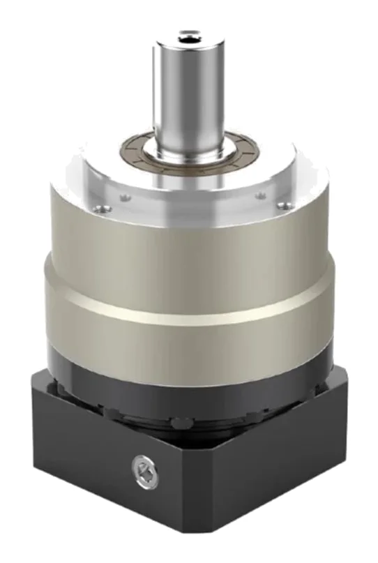
Planetary gearboxes share the load between three or more planet gears running between a sun and a ring gear. One stage typically gives 3:1 to 10:1, and two stages reach about 100:1. They are efficient, compact for their torque, widely standardised to servo motor flanges and usually the lowest-cost precision option.
Cycloidal reducers (Nabtesco RV and Sumitomo Fine Cyclo are well-known examples) drive one or more lobed discs eccentrically against a ring of pins. Many lobes are in contact at once, which gives very high stiffness, high torque density for the ratio and good overload tolerance. Single-unit ratios of about 30:1 to 160:1 are common, and some ranges go to around 280:1.
Strain-wave vs planetary vs cycloidal: comparison table
| Factor | Strain-wave | Precision planetary | Cycloidal |
|---|---|---|---|
| Backlash | Zero by design | Typically 1–3 arcmin precision; up to ~8 arcmin standard helical | Around 0.1–0.2 arcmin |
| Hysteresis / lost motion | Under 1 arcmin | Over 1 arcmin | Under 1 arcmin |
| Torsional stiffness | Moderate and non-linear (softer at low torque) | Moderate; falls with more stages | Highest of the three |
| Tilting moment capacity | Depends on output bearing; lowest of the three as a component set | Good with taper-roller output bearings | Very high, integral main bearings |
| Ratio per stage | ~30:1 to 160:1 | ~3:1 to 10:1 | ~30:1 to 160:1 (some to ~280:1) |
| Efficiency | Speed, temperature and load dependent; well below planetary at high ratio and low load | About 95% one stage, 92% two stage | Generally between the two; read the curves |
| Shock and overload | Momentary peak only for E-stops and collisions; ratcheting risk | Good within E-stop rating | Best; Nabtesco quotes up to 500% E-stop, 800% optional |
| Size and weight | Smallest and lightest; flat versions available | Compact at low ratios; grows with stages | Larger and heavier for the same torque |
| Hollow centre | Common (hollow shaft and flat sets) | Rare | Common on hollow-shaft models |
| Typical torque range | Nabtesco cites about 4.5–382 Nm as the usual band; the largest sets go to several kNm | Up to several thousand Nm | Hundreds to tens of thousands of Nm |
| Typical cost | High | Lowest | High |
Sources for the table: backlash, hysteresis, overload and torque ranges from Nabtesco and its planetary FAQ; planetary efficiency, ratios and backlash from the Apex Dynamics AE/AER catalogue; strain-wave ratios and limits from Harmonic Drive; cycloidal ratios from Sumitomo and Nabtesco RV-100N.
Backlash vs stiffness: which one matters for your axis
Engineers often specify “zero backlash” when the real requirement is position under load. Backlash is the free play you can turn the output through with no torque. Stiffness is how far the output winds up when torque is applied. A zero-backlash gear can still deflect several arcminutes under working load.
Torsional stiffness is given in Nm/rad or Nm/arcmin (1 arcmin = 2.909 × 10⁻⁴ rad, so multiply Nm/arcmin by 3,438 to get Nm/rad). Some comparison points from manufacturer data:
- Harmonic Drive CSG-25 at ratio 100 has a first-region stiffness K1 of 31 × 10³ Nm/rad (about 9 Nm/arcmin), rising in two further steps as torque increases (Harmonic Drive).
- An Apex AER120 helical planetary is listed at 11.2 Nm/arcmin (Apex Dynamics).
- A Nabtesco RV-100N cycloidal is listed at 312 Nm/arcmin torsional and 1,400 Nm/arcmin moment rigidity, for a 1,000 Nm rated torque (Nabtesco).
These are different sizes, so do not read them as a like-for-like ranking. The useful point is that stiffness scales with frame size, and cycloidal reducers give a lot of it per unit of rated torque. Strain-wave stiffness is non-linear: the K1 region at low torque is the softest, which matters for a light robot joint that spends most of its time near zero load.
Stiffness also sets the first resonant frequency of the axis, roughly f = (1/2π) × √(K / J) for a load inertia J on a gear of stiffness K. A soft gear on a heavy load lowers that frequency and limits how high you can tune the servo loop.
Ratio and efficiency
Pick the ratio first, from the motor’s useful speed and the output speed you need, then check reflected inertia. That alone often decides the type:
- Below about 30:1: a planetary is the natural choice (Nabtesco). Strain-wave and cycloidal units do not go this low in one stage.
- 30:1 to 100:1: all three are possible. A two-stage planetary gives up some backlash, stiffness and length; strain-wave and cycloidal do it in one stage.
- Above 100:1: strain-wave and cycloidal. A planetary would need three stages.
Efficiency matters for motor sizing and heat. Apex quotes 95% for one planetary stage and 92% for two. Strain-wave efficiency is published as curves against input speed and temperature, measured at rated torque, with a correction factor below rated torque. Harmonic Drive’s own worked example drops from 78% at rated torque to 73% at 57% load (Harmonic Drive). Cold starts are worse for both strain-wave and cycloidal gears, because no-load running torque rises at low temperature. Size the motor using the curve at your coldest operating temperature.
Low efficiency also helps in one way: high-ratio strain-wave and cycloidal gears are hard to back-drive, though you should never rely on that as a holding brake.
Shock, overload and life
Each gearbox has a hierarchy of torque limits. Harmonic Drive’s, for example:
- Rated torque (TN): the torque giving rated life at 2,000 rpm input.
- Limit for average torque (TA): the maximum cube-mean torque over the cycle.
- Repeatable peak torque (TR): the maximum during normal starts and stops.
- Momentary peak torque (TM): emergency stops and collisions only, never in the normal cycle.
Exceeding the limits on a strain-wave gear can cause ratcheting, where the teeth skip and the flexspline runs off-centre. Harmonic Drive warns this shortens life and can lead to flexspline fatigue failure (Harmonic Drive LLC). Cycloidal reducers are the most forgiving: Nabtesco quotes emergency-stop torque up to 500% of rated for both types, with up to 800% optional on cycloidal (Nabtesco).
Life on strain-wave and cycloidal units is governed by bearings, so it follows a cube law. For CSG gears (Harmonic Drive):
L50 = 50,000 h × (n_N / n_av) × (T_N / T_av)³
where n_N is rated input speed, n_av is average input speed, T_N is rated torque and T_av is the cube-mean output torque:
T_av = ( Σ |nᵢ| × tᵢ × Tᵢ³ / Σ |nᵢ| × tᵢ )^(1/3)
Harmonic Drive LLC quotes L10 life of 10,000 h for CSG and 7,000 h for CSF at rated conditions, with L50 five times higher (Harmonic Drive LLC). Use L10 for anything where a field failure is expensive.
Worked example 1: a cobot elbow joint
Requirement: Elbow joint for a light collaborative arm. Gravity and acceleration give 60 Nm average and 150 Nm peak at the joint. Joint speed is up to 30 rpm, average over the cycle 22 rpm. A frameless motor gives up to 3,000 rpm. The cable loom must pass through the joint centre. Target 20,000 h L10 life.
Ratio: 3,000 / 30 = 100:1. This rules out a single-stage planetary. A cycloidal unit of the right torque would be heavier and larger in diameter than a light arm wants. A hollow-shaft strain-wave gear fits.
Candidate: CSG size 25, ratio 100. Data: TN 87 Nm, TR 204 Nm, TA 140 Nm, TM 369 Nm (Harmonic Drive).
Torque checks:
- Average 60 Nm < TA 140 Nm. Pass.
- Peak 150 Nm < TR 204 Nm. Pass, with 36% margin.
- Collision torque is limited by the drive’s torque limit and the cobot’s force monitoring; it must stay under TM 369 Nm.
Life: Average input speed is 22 × 100 = 2,200 rpm.
- L10 = 10,000 × (2,000 / 2,200) × (87 / 60)³ = 10,000 × 0.909 × 3.05 ≈ 27,700 h. Pass.
Wind-up: Using the lowest stiffness region K1 = 31 × 10³ Nm/rad as a conservative figure, 60 Nm gives 60 / 31,000 = 1.9 × 10⁻³ rad, or about 6.7 arcmin. At a 0.5 m forearm that is roughly 1 mm at the tool. The real figure is lower because stiffness rises above the K1 threshold, but this is why cobot accuracy budgets need an output-side encoder or a stiffness model, not just a zero-backlash gear. See our frameless motor sizing guide for robot joints for dual encoders.
Choice: A hollow-shaft strain-wave set such as Harmonic Drive SHG or Leaderdrive LHS/LHSG at size 25, ratio 100. If axial length is tight, a flat set like CSD or Leaderdrive LHD, checked again for torque because flat sets carry less.
Worked example 2: a conveyor indexing table
Requirement: Eight-station rotary indexer on a packaging line. Load inertia 2.0 kg·m². Each 45° index must complete in 0.3 s, triangular speed profile. Friction torque about 5 Nm. Product jams happen a few times per shift. Stopping position at the station must be within ±0.25 mm at 300 mm radius.
Kinematics (θ = 45° = 0.785 rad, t = 0.3 s):
- Peak acceleration α = 4θ / t² = 4 × 0.785 / 0.09 = 34.9 rad/s²
- Peak speed ω = 2θ / t = 5.24 rad/s = 50 rpm
Output torque: J × α + friction = 2.0 × 34.9 + 5 ≈ 75 Nm peak, both accelerating and (in reverse) decelerating.
Ratio: A ratio of 20:1 puts the motor at 1,000 rpm peak and reflects 2.0 / 20² = 50 × 10⁻⁴ kg·m² to the motor, a workable mismatch for a mid-size servo. A two-stage planetary does this; strain-wave and cycloidal units would push the ratio too high or the motor speed too low.
Backlash: ±0.25 mm at 300 mm is ±0.83 × 10⁻³ rad, about ±2.9 arcmin. During deceleration the torque reverses, so the table crosses the backlash zone right before it stops. A standard 8 arcmin gearbox would use the whole tolerance on backlash alone. Specify a precision planetary at 3 arcmin or better, or 1 arcmin if a locating pin is not used.
Shock: Jams are the deciding risk. Set the drive torque limit just above 75 Nm plus margin, and check the gearbox’s emergency-stop torque covers a jam at full speed. If the table is heavy and jams are frequent, a cycloidal reducer with a two-stage arrangement or a belt pre-stage is the robust alternative.
Choice: A two-stage precision planetary such as Apex AE/AER or Wanshsin WVRB in a frame where 75 Nm sits well under the rated output torque at 20:1, with efficiency of about 92% for motor sizing.
Common mistakes
- Specifying zero backlash when you need stiffness. Check wind-up at working torque.
- Sizing on peak torque only. Check the cube-mean against the average limit, and the peaks against the repeatable limit.
- Using the strain-wave momentary peak as a design load. It is for collisions only.
- Ignoring cold efficiency. Strain-wave and cycloidal drag rises sharply at low temperature.
- Forgetting the output bearing. A strain-wave component set has no output bearing; the moment load goes into your housing design or a unit version with a cross-roller bearing.
- Stacking planetary stages to reach 100:1 and then fighting backlash and stiffness. A single-stage strain-wave or cycloidal unit is often smaller.
Checklist
Send these to our engineers, or enter them in the spec builder:
- Motor type and frame, and its speed range
- Output speed and the required ratio range
- Torque cycle: values and durations for acceleration, constant speed, deceleration and dwell
- Peak and emergency-stop or collision torque
- Backlash and allowable wind-up at working torque (arcmin)
- Load inertia, and the resonance or servo bandwidth target
- Radial, axial and tilting moment loads on the output
- Required life in hours, and the duty (shifts, cycles per hour)
- Hollow-shaft requirement and bore diameter for cables or services
- Envelope limits: diameter, axial length, mass
- Ambient temperature range, lubrication preference, IP rating
- Component set (built into your housing) or complete sealed unit
For more on the wider family, see our gearboxes overview.
Frequently asked questions
Is a harmonic drive the same as a strain-wave gear?
Harmonic Drive is a trademark of Harmonic Drive LLC and its group companies. Strain-wave gearing is the generic name for the principle: an elliptical wave generator flexes a thin toothed flexspline inside a rigid circular spline with two more teeth, giving a high ratio in one stage with no backlash. Several manufacturers make strain-wave gears, so specify by the generic term and the performance you need.
Which gearbox type has zero backlash?
Strain-wave gears have no backlash by design because the teeth are pre-loaded against each other by the wave generator. Precision cycloidal reducers are close, with Nabtesco quoting around 0.1 to 0.2 arcmin. Precision planetary gearboxes are typically around 1 to 3 arcmin, and standard helical planetaries can be up to about 8 arcmin. All three still have lost motion and elastic wind-up under load.
Why is a strain-wave gear less efficient than a planetary?
A planetary stage is mostly rolling tooth contact and reaches about 95% per stage in good designs. A strain-wave gear continuously flexes the flexspline and runs a heavily loaded wave generator bearing, so its efficiency depends strongly on speed, temperature, lubricant and load. Manufacturers publish curves rather than single values, and efficiency drops further at low torque, so read the curves at your own operating point.
Can a strain-wave gear take shock loads?
Only within its published limits. Harmonic Drive states that the momentary peak torque is for emergency stops or collisions and must never occur in the normal cycle, and that excessive torque can cause ratcheting, where the teeth skip and the gear runs off-centre, damaging the flexspline. For axes that will see jams or impacts, a cycloidal reducer or a generously sized planetary is usually the safer choice.
Which gearbox should I use for a robot joint?
Most collaborative and light-payload robot joints use strain-wave gears because they are compact, light, backlash-free and give a high ratio with a hollow centre for cables. Base and shoulder axes on larger industrial robots usually use cycloidal reducers for their stiffness, moment capacity and shock tolerance. Planetaries suit wrist or gantry axes where the ratio is low and cost matters.
How is gearbox life calculated?
Strain-wave and cycloidal life is set mainly by the bearings, so life scales with the cube of the torque ratio and inversely with speed. For Harmonic Drive CSG gears, L50 = 50,000 h × (rated input speed ÷ average input speed) × (rated torque ÷ average output torque)³. Use the cube-mean torque over the whole cycle, not the peak, and check peaks separately against the repeatable and momentary limits.
Sources
- Nabtesco: Cycloidal gears or strain wave gears, when is which the better choice?
- Nabtesco: Planetary gears FAQ
- Nabtesco: RV-100N cycloidal gearbox data
- Harmonic Drive AG: CSG-2A component sets engineering data
- Harmonic Drive LLC: CSF and CSG series catalogue
- Sumitomo Drive Technologies: Zero backlash precision gearboxes
- Apex Dynamics: AE/AER series catalogue (ManualMachine copy)
Figures are summarised from the sources above and from manufacturers' published data on the date shown. Always confirm against the current datasheet for your exact part.