
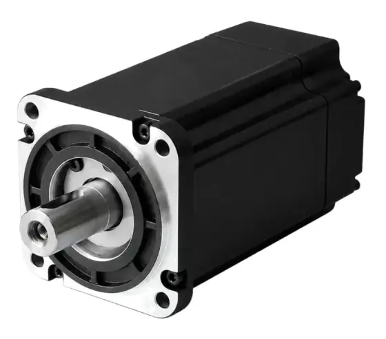
In short:A stepper motor turns a fixed angle each time its drive switches the current in its windings: a standard two-phase hybrid makes 200 full steps per revolution (1.8°). Torque is highest at standstill and falls with speed because winding inductance slows the current, so the drive's supply voltage, current setting and resonance control decide what the motor really delivers.
How a stepper motor works, in one paragraph
A stepper motor converts each electrical pulse into a fixed angle of rotation. The drive switches current through the stator windings in sequence; every switch moves the stator’s magnetic field one step, and the rotor is pulled to the next stable position. The number of pulses sets the angle and the pulse rate sets the speed (Machine Design). That is why steppers are popular for positioning: no encoder is needed to know roughly where the shaft is, as long as the motor never has to deliver more torque than it can at that speed.
This page explains the physics behind that. If you already know it and want to choose a motor, go to how to select a stepper motor; for the servo comparison see servo vs stepper.
Stepper motor types: hybrid, permanent magnet and variable reluctance
All three types use a wound stator. They differ in the rotor.
| Variable reluctance (VR) | Permanent magnet (PM, can-stack) | Hybrid | |
|---|---|---|---|
| Rotor | Soft iron, toothed, no magnet | Magnetised, no teeth | Axially magnetised with two toothed iron cups |
| Typical step angle | 5–15° | Coarse; 45° or 90° in Machine Design’s examples | 0.9–5°, most commonly 1.8° |
| Detent torque | None | Yes | Yes |
| Torque | Low | Good at low speed | Highest of the three |
| Where you meet it | Rare in new industrial designs | Low-cost actuators, valves, small mechanisms | Almost every industrial NEMA-frame stepper |
Step angles from Machine Design; torque and detent comparisons from Monolithic Power Systems.
The hybrid is the one engineers specify. Its rotor carries a permanent magnet magnetised along the shaft, sandwiched between two iron cups each cut with fine teeth. The two cups are offset by half a tooth pitch, so one presents north poles and the other south. Oriental Motor describes rotors with 50 teeth on each cup (Oriental Motor). The stator poles carry matching teeth, and the rotor moves to wherever the teeth line up with the energised poles.
The step angle formula
For a hybrid motor:
Full-step angle = 360° ÷ (2 × number of phases × rotor teeth)
- Two-phase, 50 teeth: 360 / 200 = 1.8° (200 steps per revolution)
- Five-phase, 50 teeth: 360 / 500 = 0.72° (500 steps per revolution)
- A two-phase motor with 100 teeth gives 0.9° (400 steps)
Two-phase motors are by far the most common; three- and five-phase versions exist for smoother running and finer native resolution (Monolithic Power Systems). Under no load, Oriental Motor quotes an angular accuracy within 3 arc minutes (0.05°), and the error does not accumulate from step to step.
Full step, half step and microstepping
The drive decides how finely the field moves:
- Wave drive: one phase on at a time. Simplest, least torque.
- Full step: two phases on at all times. More torque than wave drive.
- Half step: alternates between one and two phases on, halving the step angle. Torque varies from step to step because it is higher when both phases conduct.
- Microstepping: the drive sets each phase current to a sine and cosine proportion of the maximum, so the field can sit anywhere between full steps. Monolithic Power gives the example of setting phase A to 0.92 × I max and phase B to 0.38 × I max to rotate the field by 22.5° within a 90° electrical step.
Microstepping makes motion smoother and quieter and reduces low-speed resonance. It does not give you torque or accuracy in proportion to resolution. The torque that moves the rotor one microstep is:
Incremental torque = full-step holding torque × sin(90° ÷ microsteps per full step)
That is about 20% of holding torque at 1/8 step and 5% at 1/32 (Monolithic Power Systems). In their test, a 1.26 Nm motor at 1/32 step needed two microsteps before it moved against a 0.1 Nm friction load. Fine microstepping is a smoothing tool; if you need fine positioning under load, gear the motor down or use a finer native step angle.
Bipolar, unipolar and current control
Most industrial drives are bipolar: an H-bridge reverses the current in each whole winding, so all the copper works all the time. Unipolar drives use a centre-tapped winding and simpler switches, but use only half the copper at once. Monolithic Power notes bipolar is now the most popular arrangement.
Modern drives are current-controlled (chopper) drives. They apply a supply voltage many times the motor’s rated voltage and switch it on and off to regulate winding current at the set value. That is the key to performance at speed, explained next.
The torque-speed curve and pull-out torque
A stepper’s datasheet gives several torque figures, and they mean different things (Design World; Kollmorgen):
| Figure | What it is | Use it for |
|---|---|---|
| Holding torque | Torque to push an energised, stationary motor off position at rated current | Comparing motors; static holding |
| Detent torque | Residual torque with no power, from the magnets | Whether a load back-drives an unpowered motor |
| Pull-out torque | Maximum torque at a given speed before the motor loses synchronism | Sizing: this is the torque-speed curve |
| Pull-in torque | Maximum load the motor can start against, without ramping, at a given step rate | Start-stop moves without acceleration ramps |
Kollmorgen puts holding torque roughly 20% higher than the low-speed dynamic torque, so even at a crawl you do not get the full holding figure.
Why torque falls with speed. Each phase is an inductance L in series with a resistance R. Current cannot change instantly: with a fixed voltage it rises with time constant L/R, and the back-EMF the motor generates grows with speed. At low step rates the current reaches its set value well within each step, so torque is flat. As the step rate rises, the time per step shrinks until the current no longer reaches its set value, and torque falls away. Because a hybrid stepper has 50 pole pairs, its electrical frequency is 50 times the shaft speed in revolutions per second, which is why the fall begins at modest rpm.
Why supply voltage matters. The rate at which current builds is roughly V ÷ L. Doubling the supply voltage lets current rise twice as fast; Geckodrive puts it simply as doubling the voltage doubles the motor’s high-speed power (Geckodrive). Its rule of thumb for the supply is:
Supply voltage ≈ 32 × √(phase inductance in mH)
and between 4 and 20 times the motor’s rated voltage. Above that, iron losses heat the motor even though the current is regulated. A pull-out curve is only valid for the drive, supply voltage and winding connection it was measured with.
Series or parallel. Eight-lead motors can be wired with the two half-windings of each phase in series (four times the inductance of one half, lower current) or in parallel (the same inductance as one half, twice the current). Geckodrive notes a parallel-connected motor gives twice the power of a series-connected one at the same supply voltage, at the cost of a higher drive current.
Resonance in stepper motors
The rotor and load sit in a magnetic “spring” at each step position, so every step excites a small damped oscillation. Oriental Motor attributes low-speed vibration to exactly this step-like movement. Two problems follow:
- Low-speed resonance, which Kollmorgen places typically around 50 to 200 steps per second (15 to 60 rpm on a 200-step motor). Microstepping largely cures it, which is why older pull-in curves mattered more than they do now.
- Mid-range instability, at around 1,200 to 3,000 full steps per second (6 to 15 rev/s). The rotor oscillates at 50 to 150 Hz, the oscillation grows over several cycles, and the motor can stall in 0.1 to 1 second. Microstepping does not cure it; drives that sense the oscillation and add electronic damping do (Dover Motion).
Load inertia changes both: a heavier load lowers the natural frequency and can move the problem band. Test with the real mechanism, and avoid cruising inside the mid-range band unless the drive has anti-resonance control or the motor runs closed loop.
Worked example: a NEMA 23 stepper on a lead screw
The axis. A NEMA 23 two-phase hybrid stepper drives a 5 mm lead screw. Resolution needed: 0.01 mm. Traverse speed: 100 mm/s. Motor data (assumed for the example; use your datasheet): 2.0 Nm holding torque, 4.2 A per phase, 2.8 mH and 0.7 Ω per phase in parallel connection.
Resolution.
- Full step: 5 mm ÷ 200 = 0.025 mm. Not fine enough.
- 1/8 microstep: 5 ÷ 1,600 = 0.003 mm per microstep, so the 0.01 mm requirement is met with about three microsteps.
- Incremental torque at 1/8 step: 2.0 × sin(11.25°) ≈ 0.39 Nm. If friction and preload on the nut approach this, the rotor will lag a few microsteps; the 0.01 mm target is safe only if load torque at rest is well below it.
Speed and step rate.
- 100 mm/s ÷ 5 mm = 20 rev/s = 1,200 rpm
- Full-step rate: 20 × 200 = 4,000 steps/s, so 0.25 ms per full step
- 20 rev/s is above the 6–15 rev/s mid-range band, so the motor accelerates through that band on every move. Use a ramp that passes through it briskly and a drive with anti-resonance damping.
Can the current keep up?
- Winding time constant L/R = 2.8 mH ÷ 0.7 Ω = 4 ms, sixteen times longer than a 0.25 ms step. At the motor’s rated voltage (4.2 × 0.7 ≈ 2.9 V) current would barely start to rise before the next step.
- At 48 V, current rises at roughly V/L = 48 ÷ 0.0028 ≈ 17,000 A/s, so reaching 4.2 A takes about 0.25 ms, ignoring back-EMF. That is the whole step period, so torque at 1,200 rpm will already be well below holding.
- Geckodrive’s rule gives 32 × √2.8 ≈ 54 V, so a 48 V supply is a sensible choice and a 24 V supply would leave the motor short of torque at this speed.
What to do with the answer. Read the pull-out curve for this motor at 48 V in parallel connection, at 1,200 rpm, and compare it with the axis torque (friction, screw efficiency and acceleration) plus margin. If it falls short, either slow the traverse, choose a lower-inductance winding, or move to a closed-loop stepper or a servo. The sizing method is in how to select a stepper motor and the drive side in how to select a stepper drive.
Holding torque vs detent torque in practice
Holding torque needs current. If the drive reduces current at standstill (most offer idle current reduction to limit heating), holding torque falls with it, roughly in proportion. Detent torque is present without power, but it is small and is not a substitute for a brake. On a vertical axis or a back-drivable screw, fit a holding brake or use a self-locking transmission, and do not rely on detent torque to stop a load dropping at power loss.
Products in our range to consider
- M57STH NEMA 23 hybrid steppers: 57/60 mm two-phase, 1.8°, 1–4 Nm holding, mostly eight-lead for series or parallel wiring.
- M86STH NEMA 34 hybrid steppers: 86 mm frame, 2.2–11.96 Nm holding, with 0.9° and 1.2° options.
- Leadshine CM hybrid steppers: two-phase open-loop range from NEMA 8 to NEMA 52, 0.03–45 Nm holding, with encoder, brake and IP65 variants.
- Leadshine five-phase steppers: 0.72° motors in 28, 42 and 60 mm frames with ±0.036° full-step accuracy at no load.
- Leadshine 3S three-phase steppers: NEMA 23 and 34 three-phase hybrids, 0.9–6.8 Nm holding.
- Leadshine CS-M closed-loop steppers: hybrid steppers with 1,000- or 5,000-line encoders, NEMA 8 to 34.
- Leadshine iEM integrated steppers: motor and drive in one unit, NEMA 17 to 24, 0.3–3.5 Nm.
- DINGS captive linear steppers: hybrid steppers with an integrated acme lead screw and anti-rotation, up to 2,400 N.
Checklist
Before you choose or brief a supplier on a stepper, have these answers ready, or enter them in the spec builder:
- Required resolution at the load, and the transmission (screw lead, belt pulley, gearbox ratio)
- Highest speed and the speed you spend most time at, in rev/s at the motor
- Whether the cruise speed sits in the 6–15 rev/s mid-range band
- Torque at the highest speed, including acceleration, friction and gravity, with margin
- Supply voltage available, and the phase inductance of candidate motors
- Winding connection for eight-lead motors: series or parallel
- Microstep setting and the incremental torque at that setting
- Standstill requirement: holding torque at reduced idle current, or a brake
- Whether lost steps are acceptable; if not, consider closed loop
- Environment, frame size and connector or IP needs
For the rest of the family, see servo and stepper motors, and for the servo side of the theory, how servo motors work.
Frequently asked questions
How does a stepper motor work?
The drive energises the stator windings in a fixed sequence. Each change of current moves the stator's magnetic field by a set angle, and the toothed or magnetised rotor follows it to the next stable position. Count the pulses and you know the angle; set the pulse rate and you set the speed. Classic steppers run open loop, so the controller assumes the rotor followed.
Why is a hybrid stepper 1.8° per step?
A typical hybrid rotor has 50 teeth on each of two magnetised cups, offset by half a tooth. On a two-phase motor the full-step angle is 360° divided by (2 × phases × rotor teeth): 360 / (2 × 2 × 50) = 1.8°, or 200 steps per revolution. The same 50-tooth rotor in a five-phase motor gives 0.72°, which Oriental Motor's five-phase motors use.
What is the difference between holding torque and detent torque?
Holding torque is the torque needed to push an energised motor off position at rated current and zero speed. Detent torque is the smaller residual torque you feel turning the shaft by hand with no power applied, caused by the permanent magnets attracting the stator teeth. Variable reluctance motors have no magnet and therefore no detent torque. Neither figure tells you the torque available at speed.
Does microstepping make a stepper more accurate?
It makes it smoother and finer in resolution, not necessarily more accurate. The torque that moves the rotor one microstep is the full-step holding torque times sin(90° / microsteps): about 20% at 1/8 step and 5% at 1/32, according to Monolithic Power Systems. Under friction or load the rotor may not move until several microsteps have accumulated.
Why does a stepper lose torque at high speed?
Each winding is an inductor. At higher step rates there is less time for current to build to its set level before the drive switches it again, and the motor's back-EMF rises with speed too. Average current, and therefore torque, falls. A higher supply voltage forces current in faster, which is why the same motor holds torque to a higher speed on a 48 V drive than on 24 V.
What causes stepper motor resonance?
The rotor and load behave like a mass on a magnetic spring, so each step causes a small damped oscillation. At low speed this shows as rough running, typically around 50 to 200 steps per second according to Kollmorgen. A separate mid-range instability at about 6 to 15 rev/s can stall the motor; drives with electronic damping, or closed-loop control, suppress it.
Sources
- Monolithic Power Systems: Stepper motors basics, types, uses and working principles
- Machine Design: Stepper basics
- Oriental Motor: Technical reference
- Design World: What are the four torque characteristics associated with stepping motors?
- Kollmorgen: Pull-in and pull-out torque
- Monolithic Power Systems: Why microstepping isn't as good as you think
- Dover Motion: Midrange resonance
- Geckodrive: G203V step motor drive manual (power supply selection)
Figures are summarised from the sources above and from manufacturers' published data on the date shown. Always confirm against the current datasheet for your exact part.