
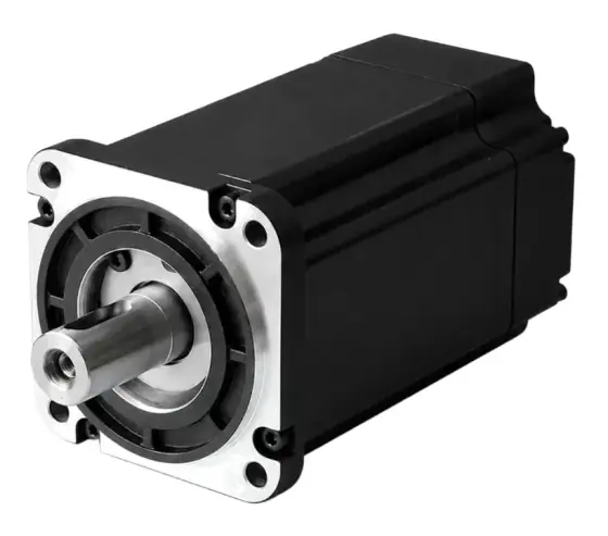
In short:Pick a hybrid stepper for almost any OEM axis, size it on pull-out torque at your operating speed with a safety factor of 1.5 to 2 (not on holding torque), keep the load inertia within about 10 times the rotor, then choose the winding and supply voltage so the drive can push current in at speed. Go closed-loop when a lost step would cost you a part.
The selection sequence
Choose in this order, because each decision constrains the next:
- Confirm a stepper is right. Steppers suit short, repeated moves at low to moderate speed with simple control. For high speed, high dynamics or unknown loads, read servo vs stepper first.
- Choose the type: hybrid or permanent magnet (PM), two-phase or five-phase.
- Calculate load torque and inertia at the motor shaft, including gearing.
- Choose frame and stack from the pull-out curve at your speed, with margin; check inertia ratio.
- Choose winding and supply voltage so the drive reaches rated current at speed.
- Choose the drive, then open loop, closed loop or integrated.
- Add options: brake, encoder, gearhead, IP rating, shaft and connector.
Hybrid vs permanent magnet steppers
Hybrid steppers combine a toothed, variable-reluctance style rotor with a permanent magnet, giving both fine steps and good torque for their size (ROHM). The standard is 1.8° (200 full steps per revolution), with 0.9° versions for finer native resolution. Five-phase hybrids step at 0.72° (500 steps per revolution) and run more smoothly at the cost of a matching five-phase drive (Oriental Motor). For industrial OEM axes, a two-phase hybrid is the default.
PM (can-stack) steppers use a magnetised rotor without fine teeth. They are cheap and compact but have coarse steps, commonly 7.5° or 15°, and modest torque, so they suit valves, dampers and indicators rather than production machine axes.
NEMA frame size: what it does and doesn’t tell you
NEMA frame numbers describe the faceplate in tenths of an inch: NEMA 17 is about 42 mm square, NEMA 23 about 57 mm and NEMA 34 about 86 mm. The number standardises mounting dimensions so motors are interchangeable on the flange (Kollmorgen). It does not standardise torque.
Within one frame, torque scales with stack length, so the frame is a packaging decision and the stack and winding are the performance decision. Rough guidance:
| Frame | Approx. face | Typical holding torque range | Typical uses |
|---|---|---|---|
| NEMA 8–14 | 20–35 mm | 0.01–0.45 Nm | Lab instruments, optics, small pumps |
| NEMA 17 | 42 mm | 0.2–0.7 Nm | Printers, small XY stages, dispensing |
| NEMA 23 | 57 mm | 1–4 Nm | Packaging, labelling, light CNC, indexers |
| NEMA 34 | 86 mm | 2–12 Nm | Heavier axes, feeders, rotary tables |
| NEMA 42 | 110 mm | 11–33 Nm | High-torque, low-speed industrial drives |
Ranges are from the series in our catalogue data; other makers differ.
Holding torque vs pull-out torque
Four torque figures appear on stepper datasheets (Design World):
- Holding torque: the torque needed to move the energised motor at standstill. It is roughly torque constant × current and is the headline figure, but it is not on the torque-speed curve. Kollmorgen notes it is generally about 20% above the motor’s low-speed dynamic torque (Kollmorgen).
- Pull-out torque: the maximum torque the motor can deliver at each speed while staying in synchronism. This is the curve you size against.
- Pull-in torque: the load the motor can start against at a given step rate without ramping. With modern ramped profiles it matters less.
- Detent torque: the small cogging torque with the motor unpowered. It is not a holding brake.
Size on pull-out torque at the speed of the hardest segment of the move, using the curve published for the drive and supply voltage you will actually use. A curve measured at 48 V tells you little about the same motor at 24 V.
Required motor torque = (load torque + acceleration torque) × safety factor, with Oriental Motor using a safety factor of 1.5 to 2 (Oriental Motor). Acceleration torque is (J_rotor + J_load reflected) × α. With gearing of ratio i, reflected inertia is J_load ÷ i² and reflected load torque is T_load ÷ (i × η).
Inertia ratio
Open-loop steppers have no way to correct an overshoot, so a heavy load relative to the rotor makes them stall or ring during acceleration. Oriental Motor’s sizing reference gives maximum load-to-rotor inertia ratios of about 10 for one standard range and 30 for its closed-loop range, and recommends a gearhead above these (Oriental Motor). Treat 10:1 as a sensible design target for open-loop hybrids unless the maker’s guidance says otherwise. Reduction is the usual fix, because reflected inertia falls with the square of the ratio.
Phase current, inductance and supply voltage
This is where most stepper selections go wrong. The winding is an inductor; at speed, each step lasts so briefly that current cannot rise to its set value unless the drive has voltage to spare. Torque falls off as speed rises because current does.
- Chopper drives solve this by running from a supply well above the motor’s nameplate voltage and chopping to hold the set current; Motion Control Tips cites typically eight times nominal (Motion Control Tips). The nameplate voltage on a stepper is just rated current × winding resistance. It is not the supply voltage.
- A rule of thumb for maximum supply voltage is 32 × √L, with L in millihenries. Geckodrive gives this rule, with the example of a 2 mH motor suiting about 45 V, and says the supply should be between 4 and 20 times the motor’s rated voltage (Geckodrive).
- Low-inductance windings keep torque to a higher speed at a given voltage, but need more current, so a bigger drive.
- Eight-lead motors can be wired in series or parallel. Series doubles the turns, so inductance rises about four times and the current rating halves; good low-speed torque from a small drive. Parallel gives about twice the power at the same supply voltage and better high-speed torque, at higher current (Geckodrive).
If the machine has a 24 V supply only, choose a low-inductance winding. If you have 48 V or more, you can use a higher-inductance, lower-current winding and a smaller drive.
Microstepping: resolution, not accuracy
Microstepping drives shape the phase currents as sine and cosine to divide each full step into smaller ones. It smooths motion and reduces low-speed vibration. It does not add torque or guarantee accuracy.
The incremental torque available to move one microstep is the holding torque × sin(90° ÷ X), where X is the number of microsteps per full step. At 1/8 step that is about 20% of holding torque; at 1/32 step about 5% (Monolithic Power Systems). Any friction or load torque larger than that is absorbed as position error until enough microsteps have accumulated. In MPS’s tests, a load above the incremental torque caused microsteps to be skipped or delayed.
So pick a microstep setting for smoothness, and for finer real resolution use a 0.9° motor, gearing, a finer lead or a closed-loop motor.
Resonance
Steppers have two resonance problems:
- Low-speed resonance around the motor’s natural frequency, which Kollmorgen puts at typically 50 to 200 steps per second, or 15 to 60 rpm (Kollmorgen). Microstepping and load damping largely cure it.
- Mid-range resonance, which Dover Motion places at roughly 1,200 to 3,000 full steps per second (6 to 15 rev/s on a 1.8° motor). The oscillation can build over a few cycles and stall the motor within 0.1 to 1 s, and microstepping alone does not fix it (Dover Motion).
Specify a drive with electronic anti-resonance or damping if the move runs through that band, avoid dwelling at the problem speed, and test with the real load. Closed-loop operation also suppresses resonance.
Closed-loop and integrated steppers
A closed-loop stepper adds an encoder and a drive that commutates from the rotor position, so it detects and corrects deviation instead of losing steps silently. Nanotec describes open-loop designs needing torque margins often up to 50%, and closed-loop operation as practically resonance-free (Nanotec). Because current follows load rather than sitting at full value, closed-loop steppers run cooler; Applied Motion reported a test in which a closed-loop system used as little as one-third of the power of an equivalent open-loop system (Machine Design).
An integrated stepper puts the drive (and often a controller, encoder and fieldbus) on the back of the motor. It saves cabinet space and motor cables and suits distributed machines and AGVs. The trade-offs are heat at the motor, a fixed supply range (often 24 to 48 V or 60 V) and replacing the whole unit if the electronics fail.
Matching a stepper drive
- Current: covers the motor’s phase current in the chosen wiring; check whether the drive is rated in RMS or peak (peak = RMS × 1.414).
- Voltage: covers the supply from the inductance rule, with headroom for regeneration.
- Phases: two-, three- and five-phase motors each need a matching drive.
- Interface: pulse and direction, Modbus RTU, CANopen, EtherCAT, EtherNet/IP or an onboard indexer.
- Features: idle current reduction, anti-resonance, brake and fault outputs, STO if needed.
Worked example: a 6-station rotary indexer
Application: a 300 mm aluminium dial, 12 mm thick, carries six 0.2 kg fixtures at 120 mm radius. It indexes 60° in 0.3 s, then dwells 0.5 s. Bearing drag at the dial is 0.5 Nm. The machine has a 48 V DC bus.
Load inertia:
- Dial mass: π × 0.15² × 0.012 × 2,700 ≈ 2.29 kg; J = ½ × 2.29 × 0.15² ≈ 0.0258 kg·m²
- Fixtures: 6 × 0.2 × 0.12² ≈ 0.0173 kg·m²
- Total J_load ≈ 0.0431 kg·m²
Direct drive would need a huge rotor to keep the inertia ratio sensible, so use a 10:1 reduction (planetary gearhead or belt, η ≈ 0.9 assumed). Reflected inertia: 0.0431 ÷ 10² = 4.31 × 10⁻⁴ kg·m².
Move profile at the motor (1/3 trapezoid):
- Motor travel: 60° × 10 = 600° = 1.67 rev in 0.3 s
- Peak speed: 1.5 × 1.67 ÷ 0.3 ≈ 8.3 rev/s (500 rpm)
- α = 2π × 8.3 ÷ 0.1 ≈ 524 rad/s²
Torque at the motor:
- Assume a NEMA 23 rotor inertia of 0.48 × 10⁻⁴ kg·m² (check the datasheet for the actual motor).
- Acceleration: (4.31 + 0.48) × 10⁻⁴ × 524 ≈ 0.25 Nm; ÷ 0.9 ≈ 0.28 Nm (conservative, applying η to the whole term)
- Friction: 0.5 ÷ (10 × 0.9) ≈ 0.06 Nm
- Total ≈ 0.34 Nm; with a safety factor of 2, 0.67 Nm of pull-out torque at 500 rpm
Inertia ratio: 4.31 ÷ 0.48 ≈ 9:1. Inside the 10:1 target. Without the gearhead it would be about 900:1.
Motor choice: a NEMA 23 hybrid whose pull-out curve at 48 V shows at least 0.67 Nm at 500 rpm. A 1.2 to 2 Nm holding torque stack usually has that, but confirm on the curve rather than the holding figure.
Winding and voltage: for a 48 V supply, the 32 × √L rule suggests an inductance up to about (48 ÷ 32)² ≈ 2.25 mH or higher. A winding near 2 to 3 mH is a good fit; a 10 mH winding would lose torque well before 500 rpm.
Resonance: 8.3 rev/s is 1,670 full steps/s, inside Dover’s mid-range resonance band. Specify a drive with anti-resonance and test with the dial fitted.
Resolution: 1.8° at the motor is 0.18° at the dial before microstepping. That is ample for indexing; 1/8 microstepping is plenty for smoothness.
Open or closed loop: if a missed index would crash tooling, choose the closed-loop version of the same frame. It also runs cooler during the 0.5 s dwells.
What changes the answer: with a 5:1 reduction, the inertia ratio rises to about 36:1, beyond open-loop guidance, although peak motor speed falls to 250 rpm. Halving the index time to 0.15 s quadruples the acceleration torque and doubles the speed, which is the point to look at a servo.
Products in our range to consider
- NEMA 17 High Torque (M42STH): 42 mm two-phase hybrid in 29–60 mm lengths, 0.18–0.7 Nm holding torque.
- NEMA 23 High Torque (M57STH / M60STH): 57/60 mm hybrid, 1–4 Nm, mostly 8-lead for series or parallel wiring.
- NEMA 34 High Torque (M86STH): 86 mm hybrid with 22 windings from 2.2 to about 12 Nm.
- Leadshine CM Series: two-phase open-loop hybrids from 20 to 130 mm frames, up to 45 Nm, with encoder, brake and IP65 variants.
- Leadshine CS-M Series: closed-loop steppers with built-in encoders, NEMA 8 to 34, up to 12 Nm holding torque.
- Leadshine iCS Series: integrated closed-loop stepper with 14-bit encoder and onboard drive, NEMA 17–24, up to 3.5 Nm.
- Novanta IMS Liberty MDrive: integrated stepper in NEMA 17/23/34 with optional controller, closed loop and fieldbuses including EtherNet/IP and PROFINET.
- Leadshine EM-S Series: digital pulse/direction stepper drives from 1.5 to 8.2 A with anti-resonance and idle current reduction.
- Leadshine CS3E Series: closed-loop EtherCAT stepper drive up to 8 A and 110 V DC.
What else the build needs
- Drive and power supply: matched to phase current and the inductance rule; see servo drives for low-voltage drives.
- Controller: a PLC, indexer or motion controller.
- Gearing: a planetary gearhead to fix inertia ratio or multiply torque; see gearboxes and harmonic vs planetary vs cycloidal.
- Feedback: an encoder for closed loop or stall detection; see encoders.
- Brake: on any vertical axis, because detent torque will not hold a load.
- Cabling: shielded motor cable, kept apart from encoder cables.
- Slip ring: if the stepper rides on a continuously rotating table; see slip rings.
- For linear axes, see how to size a linear actuator and the servo and stepper motors hub.
Things that catch engineers out
- Sizing on holding torque. The motor that holds 1.2 Nm may give a fraction of that at the speed you need.
- Reading a torque curve measured at a different voltage or drive.
- Treating the nameplate voltage as the supply voltage. It is only I × R.
- Expecting microstepping to fix accuracy or add holding stiffness under load.
- Running through mid-range resonance on the bench without the real load, then finding stalls on the machine.
- Ignoring heat. Open-loop steppers draw full current at standstill and run hot even when doing no work; check the motor’s temperature limits against what it is mounted to, and enable idle current reduction.
- Assuming detent torque will hold a vertical load during a power cut.
- Large inertia mismatch on open-loop motors, especially direct-driven dials and pulleys.
Checklist
Send these to our engineers, or enter them in the spec builder:
- Load: mass, inertia or geometry, and any friction or process torque
- Transmission: direct, belt, gearhead or screw, with ratio or lead
- Move profile: distance, time, dwell, and cycle rate
- Required resolution and repeatability
- Holding requirement at standstill and with power off
- Supply voltage available (24 V, 48 V, mains)
- Open loop, closed loop or integrated; control interface or fieldbus
- Frame or envelope limits, shaft and connector preferences
- Environment: temperature, IP rating, washdown
- Annual volume and any existing motor you are replacing
Frequently asked questions
Should I size a stepper motor on holding torque?
No. Holding torque is measured at standstill with rated current and is not on the torque-speed curve. Kollmorgen notes it is typically around 20% higher than the motor's low-speed dynamic torque, and torque falls further as speed rises. Size on the pull-out torque curve at your operating speed, with the drive and supply voltage you will actually use, and add a safety factor of 1.5 to 2.
What does NEMA 17, 23 or 34 mean on a stepper motor?
It is a frame size that fixes the faceplate and mounting dimensions: roughly 1.7, 2.3 and 3.4 inches square, or about 42, 57 and 86 mm. It does not fix torque, length, winding or shaft details beyond the standard. Two NEMA 23 motors can differ several times over in torque depending on stack length and winding, so always compare the torque-speed curves.
What supply voltage should I use for a stepper motor?
Chopper drives use a supply well above the motor's nameplate voltage so current can rise quickly in the inductive winding at speed. A widely used rule from Geckodrive is a maximum of 32 times the square root of the winding inductance in millihenries, so a 2 mH motor suits roughly 45 V. Stay inside the drive's rating and remember higher voltage also raises motor heating.
Does microstepping increase stepper motor accuracy?
It increases resolution and smoothness, not necessarily accuracy. The incremental torque available per microstep is the holding torque multiplied by sin(90° ÷ microsteps per full step), so at 1/32 step it is only about 5% of holding torque. Any load torque larger than that can absorb several microsteps before the shaft moves. Treat high microstep settings as a smoothness tool.
When should I use a closed-loop stepper instead of open loop?
Use closed loop when a missed step must be detected or prevented, when the motor runs hot at full current, or when you want to use more of the torque curve. An encoder lets the drive correct position and set current to the load rather than running full current all the time. If you also need high speed, high dynamic response or large inertia mismatch, look at a servo instead.
What inertia ratio is acceptable for a stepper motor?
Oriental Motor's sizing reference gives maximum load-to-rotor inertia ratios of around 10 for one of its standard stepper ranges and 30 for its closed-loop range, and recommends a gearhead when these are exceeded. Lower ratios give faster settling and less risk of stalling during acceleration. If you are well above 10 on an open-loop stepper, add reduction or move up a frame.
Sources
- Oriental Motor: Technical reference, motor sizing and selection
- Kollmorgen: Pull-in and pull-out torque
- Design World: The four torque characteristics of stepping motors
- Monolithic Power Systems: Why microstepping isn't as good as you think
- Dover Motion: Midrange resonance
- Geckodrive: G203V stepper drive manual (supply voltage and wiring guidance)
- Motion Control Tips: L/R and chopper stepper drives
- Nanotec: Closed-loop technology for stepper motors
- Machine Design: Closing the loop for more energy-efficient step motor operation
- Kollmorgen: NEMA frame size
- ROHM TechWeb: Stepping motor types
Figures are summarised from the sources above and from manufacturers' published data on the date shown. Always confirm against the current datasheet for your exact part.