
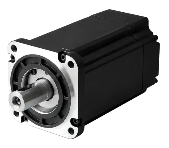
In short:An industrial servo motor is a permanent-magnet synchronous motor (PMSM) with an encoder: the drive reads rotor position, commutates the three-phase stator current so it always pulls at right angles to the magnets, and closes current, velocity and position loops around it. Torque is proportional to current through the torque constant Kt, continuous torque is set by heat, and peak torque by the drive's current and the motor's magnetic limits.
What a servo motor is
In industrial motion control, “servo motor” almost always means a permanent-magnet synchronous motor (PMSM) with a position encoder, run by a servo drive that closes control loops on that encoder. The motor makes torque; the drive decides how much, in which direction and when. Neither is a servo on its own.
That separates it from the hobby RC servo (a geared DC motor with a potentiometer) and from a stepper motor, which moves in fixed steps without needing feedback. This page explains how the motor and loops work. To choose one, see how to select a servo motor and how to select a servo drive.
PMSM construction: magnets on the rotor, copper in the stator
A servo motor is turned inside out compared with a brushed DC motor:
- Rotor: a steel shaft and core carrying rare-earth permanent magnets, either bonded to the surface or buried in slots. The magnets give a constant rotor flux (Texas Instruments).
- Stator: a laminated steel core with a three-phase winding, distributed so the back-EMF is sinusoidal. Because all the copper, and therefore all the heat, is in the stator, it conducts straight to the housing and flange. This is why a servo’s continuous rating depends on how well it is mounted.
- Feedback device: an encoder or resolver on the back of the shaft, from 2,500-line incremental to 23-bit absolute and above on current ranges.
- Options: a spring-applied holding brake, an oil seal, and a thermal sensor in the winding.
Poles and electrical frequency. The rotor has a number of magnet pole pairs, p. The electrical frequency the drive must produce is f = p × rpm ÷ 60. A ten-pole (five pole-pair) motor at 3,000 rpm needs 250 Hz. Servo motors typically have far fewer poles than a stepper’s 50 pole pairs, which is a large part of why they keep their torque to much higher speeds.
Low and high inertia. Manufacturers offer the same frame with different rotor designs. Kinco, for example, lists small-inertia motors from 0.023 to 1.027 kg·cm² and large-inertia motors from 11.56 to 140 kg·cm² in its SMK range. Low-inertia rotors suit fast, light axes; high-inertia rotors are easier to tune on heavy or compliant loads.
Commutation: steering the current to follow the rotor
A brushed motor commutates mechanically. A brushless motor relies on the drive to switch current into the right phases as the rotor turns, which is why it needs rotor position.
| Method | Position source | How it works | Result |
|---|---|---|---|
| Six-step (trapezoidal) | Three Hall sensors | Two phases conduct at a time; the pattern changes every 60 electrical degrees | Six torque ripples per electrical cycle; simple and cheap |
| Sinusoidal | Encoder or resolver | Each phase current follows a sine wave locked to rotor angle | Continuous commutation, much lower ripple |
| Field-oriented control (FOC) | Encoder, resolver or observer | Currents controlled in the rotor’s frame of reference | Smooth torque, best dynamic response and efficiency at speed |
Six-step figures from Motion Control Tips, which also notes FOC gives higher efficiency and extends speed beyond the limits of plain sinusoidal commutation, at greater complexity.
How FOC works, without the maths. The drive measures the phase currents and converts them, using the encoder angle (Clarke and Park transforms), into two DC quantities fixed to the rotor:
- Iq, at right angles to the magnets, which produces torque
- Id, in line with the magnets, which strengthens or weakens the field
For a permanent-magnet motor the drive normally holds Id at zero, because the magnets already supply the flux, and controls Iq to set torque. The motor then behaves like a separately excited DC motor with one current for torque (Texas Instruments). Torque is greatest when stator and rotor fields are kept in quadrature, which is exactly what FOC maintains.
Commutation alignment. The drive must know where electrical zero is relative to the encoder. Absolute encoders and Hall sensors give this at power-up. With an incremental encoder and no Halls, the drive runs a phase-finding routine at each power-up, which moves the shaft slightly: a problem on a vertical axis or a clamped mechanism.
Feedback: what the encoder does
The encoder serves three functions at once: commutation angle, velocity (by differentiating position) and position. Resolution affects all three. A coarse encoder gives a noisy velocity signal at low speed, which limits how high the velocity-loop gain can be set and causes the shaft to dither by a count or two at standstill. Higher resolution gives smoother low-speed motion and stiffer holding. For encoder types and interfaces, see how to select an encoder and absolute vs incremental encoders.
Current, velocity and position loops
A servo drive nests three control loops:
- Current (torque) loop, innermost. Regulates the motor current, and so the torque, to the demand from the velocity loop. With FOC there are two current regulators, for Id and Iq.
- Velocity loop. Compares commanded and measured speed and sets the torque demand.
- Position loop, outermost. Compares commanded and measured position and sets the velocity demand.
Each inner loop must respond faster than the one around it, or it has little effect. Motion Control Tips gives the rule that each inner loop should be about 5 to 10 times the bandwidth of the loop outside it (Motion Control Tips). For overall motion bandwidth, Advanced Motion Controls puts standard servo systems below about 15 Hz, large systems at 1 to 2 Hz and direct-drive systems up to about 50 Hz (A-M-C).
What limits bandwidth in practice is the mechanics. Belts, couplings and gearboxes add compliance, and their resonances force the loop gains down. That is the real reason inertia ratio and stiffness matter, and the reason direct-drive and frameless motors achieve the highest bandwidths.
Tuning order. Tune the current loop first (usually fixed by the drive maker for a matched motor), then velocity, then position, as Texas Instruments’ application note recommends for the current and speed loops. Modern drives auto-tune well on stiff mechanics; budget commissioning time for compliant or variable loads. Feed-forward of velocity and acceleration reduces following error without raising loop gains.
Torque constant, back-EMF and winding choice
Torque = Kt × current. The torque constant Kt (Nm/A) is set by the magnet strength, number of turns and geometry. The same motor generates a back-EMF proportional to speed, through the back-EMF constant Ke. In consistent SI units (Nm/A and V·s/rad) the two are numerically equal (Motion Control Tips). Datasheets often give Ke in V per 1,000 rpm, line-to-line, peak or RMS, and Kt per RMS amp; check the convention before converting.
The consequence for winding choice:
- A high-Kt winding gives more torque per amp, so a smaller drive, but more back-EMF per rpm, so a lower top speed on a given DC bus.
- A low-Kt winding reaches higher speed on the same bus but needs more current for the same torque.
The motor runs out of speed when back-EMF plus the resistive and inductive voltage drops approach the DC bus voltage. That is why the same frame is listed at 220 V and 400 V, or wound for a 48 V bus in low-voltage DC servo ranges.
Motor constant Km (Nm/√W) measures torque per square root of copper loss. Copper loss at a given torque is (T ÷ Km)², so it is the figure to compare when heat is the constraint.
Peak vs continuous torque
- Continuous (rated or stall) torque is what the motor can deliver indefinitely without the winding exceeding its insulation temperature, at the stated ambient and mounting flange. Copper loss rises with the square of current, so a motor at 120% of rated torque makes 44% more copper loss.
- Peak torque is available for short bursts, typically a few hundred milliseconds to seconds. It is limited by the drive’s peak current, by magnetic saturation (Kt falls at high current, so torque is less than linear) and by the current at which the magnets begin to demagnetise. Leadshine’s ELM motors quote up to 3.5 times overload, and its ELVM low-voltage range up to 300%.
Size the motor’s continuous rating against the RMS torque over the whole cycle, and its peak rating against the highest instantaneous torque, at the speed it occurs. Both must lie inside the torque-speed curve at your actual bus voltage. The RMS method and a full worked sizing are in how to select a servo motor.
Inertia matching
The inertia ratio is load inertia reflected to the motor shaft divided by rotor inertia. A 1:1 match theoretically gives the best acceleration control, but is rarely practical; sizing guidelines commonly suggest 10:1 or lower, and the more compliant the mechanics, the lower the ratio should be (Motion Control Tips). A high ratio shows up as overshoot, ringing and a loop that will not take high gains.
There are two ways to bring the ratio down: a gearbox, which divides reflected load inertia by the ratio squared, or a larger, higher-inertia motor, which Motion Control Tips says is rarely the better long-term answer because of cost and energy use. Equally, a ratio far below 1:1 usually means the motor is oversized.
Worked example: a direct-coupled index table
The axis. A 400 W, 60 mm servo drives an index table. Assumed motor data for the example: rated torque 1.27 Nm, peak 3.8 Nm, rated speed 3,000 rpm, Kt = 0.5 Nm/A RMS, ten poles, rotor inertia 0.5 kg·cm². Table inertia 40 kg·cm². Required: 90° index in 0.2 s.
Inertia ratio, direct drive. 40 ÷ 0.5 = 80:1. Well beyond the 10:1 guideline; the axis would be hard to tune and slow to settle.
Add a 5:1 low-backlash gearbox. Reflected table inertia = 40 ÷ 5² = 1.6 kg·cm². Add an assumed gearbox inertia of 0.1 kg·cm²: ratio ≈ (1.6 + 0.1) ÷ 0.5 = 3.4:1. Comfortable.
Motion. A triangular profile, 0.1 s accelerate, 0.1 s decelerate, over 90° (1.571 rad) at the table:
- Table angular acceleration: α = 4θ ÷ t² = 4 × 1.571 ÷ 0.04 ≈ 157 rad/s²
- Peak table speed: α × 0.1 = 15.7 rad/s = 150 rpm, so 750 rpm at the motor
- Motor acceleration: 157 × 5 = 785 rad/s²
Torque at the motor. Total inertia at the motor = 1.6 + 0.1 + 0.5 = 2.2 kg·cm² = 2.2 × 10⁻⁴ kg·m².
- Acceleration torque: 2.2 × 10⁻⁴ × 785 ≈ 0.17 Nm, plus friction. Comfortably inside 3.8 Nm peak.
- Current at that torque: 0.17 ÷ 0.5 ≈ 0.35 A RMS. The motor is lightly loaded, so a 200 W frame might do; check its rotor inertia keeps the ratio sensible.
Electrical frequency. Five pole pairs at 750 rpm: 5 × 750 ÷ 60 = 62.5 Hz, well within the drive’s capability. At 3,000 rpm it would be 250 Hz.
What the example shows. Direct coupling looked simpler, but the inertia ratio would have dominated the result. The gearbox fixed it, at the cost of backlash and compliance, which is the trade-off that leads high-precision tables to housed direct-drive or frameless torque motors. For gearbox choice see harmonic vs planetary vs cycloidal.
Products in our range to consider
- Kinco SMK AC servo motors: 50 W to 7.5 kW, up to 47.8 Nm rated and 119.5 Nm peak, 23-bit multi-turn absolute encoders as standard.
- Kinco SMH AC servo motors: 40–180 mm frames to 48 Nm rated, 2,500-line encoder with Hall commutation as standard, resolver option on the 180 mm frame.
- Leadshine ELM AC servo motors: 50 W to 7.5 kW, 23-bit absolute encoders, IP65 or IP67 and up to 3.5 times overload.
- Leadshine EL8 AC servo drives: 400 W to 2 kW, 12 A continuous and 36 A peak, matched to ELM motors.
- Leadshine ELVM low-voltage servo motors: PMSM motors for 24–60 V buses, 33 W to 2 kW, to 16 Nm peak.
- Leadshine iSV2 integrated servo motors: 200–750 W motor and drive units on 24–48 VDC, 0.64–2.39 Nm rated and up to 7.2 Nm peak.
- Novanta Everest servo drives: compact 8–72 VDC drives to 45 A continuous, with BiSS-C, SSI and Hall feedback inputs.
Checklist
Have these ready before choosing a servo motor or briefing our engineers, or use the spec builder:
- Move profile: distance, time, dwell and cycle rate
- Load inertia and the transmission between load and motor
- RMS and peak torque at the motor, and the speed at which the peak occurs
- Supply: mains AC (single or three phase) or a 24/48 V DC bus
- Inertia ratio target, given how stiff the mechanics are
- Feedback: absolute or incremental, resolution, and whether Halls are needed
- Whether phase-finding motion at power-up is acceptable
- Brake for vertical or back-driven axes
- Mounting surface and ambient temperature (they set the continuous rating)
- Drive command interface: pulse, analogue, CANopen, EtherCAT, EtherNet/IP
- IP rating, shaft seal and connector style
For more, see the servo and stepper motors and servo drives hubs, and compare with brushed vs brushless motors.
Frequently asked questions
How does a servo motor work?
A servo motor has permanent magnets on the rotor and a three-phase winding in the stator. An encoder tells the drive exactly where the rotor is, so the drive can feed the winding currents that produce a magnetic field at 90 electrical degrees to the magnets, which gives the most torque per amp. The drive then compares commanded and measured position and speed many thousand times a second and adjusts the current to correct any error.
What is the difference between a BLDC motor and a PMSM servo?
Both are brushless permanent-magnet motors. A BLDC motor is usually wound for a trapezoidal back-EMF and driven with six-step commutation from three Hall sensors, which updates every 60 electrical degrees and gives six torque ripples per electrical cycle. A PMSM servo is wound for a sinusoidal back-EMF and driven with sinusoidal or field-oriented control from an encoder, which gives smooth torque down to zero speed.
What is field-oriented control?
Field-oriented control (FOC) measures the phase currents, transforms them into two components aligned with the rotor (d-axis, along the magnets, and q-axis, at right angles), and controls each separately. For a permanent-magnet motor the d-axis current is normally held at zero, as Texas Instruments' application note SPRABY9 notes, and the q-axis current sets torque. The motor then behaves much like a DC motor with a single torque current.
What is a servo motor's torque constant?
The torque constant Kt is torque per amp of current, in Nm/A. It is fixed by the magnets, the number of turns and the geometry. In consistent SI units it is numerically equal to the back-EMF constant Ke in V·s/rad. A higher Kt gives more torque per amp but more back-EMF per rpm, so the same frame is offered in several windings trading torque per amp against top speed.
Why does a servo have both a peak and a continuous torque rating?
Continuous torque is the torque the motor can deliver indefinitely without the winding exceeding its temperature limit, at a stated ambient and mounting. Peak torque is available for short bursts, limited by drive current, magnetic saturation and the risk of demagnetising the magnets. Leadshine's ELM motors, for example, quote up to 3.5 times overload. Size continuous torque on the RMS of the duty cycle and peak on the worst instant.
What inertia ratio should I aim for with a servo motor?
Motion Control Tips cites sizing guidelines of 10:1 or lower (load inertia reflected to the motor shaft divided by rotor inertia), and notes there is no single formula. The more compliant the mechanics (belts, couplings, long shafts), the lower the ratio should be. A gearbox divides reflected load inertia by the ratio squared, which is usually a better fix than a larger, higher-inertia motor.
Sources
- Texas Instruments: Sensorless field oriented control of 3-phase PMSMs (SPRABY9)
- Motion Control Tips: What are ways to avoid torque ripple in DC motors?
- Motion Control Tips: Difference between torque, back-EMF and motor constant
- Motion Control Tips: Why is the bandwidth of a servo control loop important?
- Advanced Motion Controls: What is servo bandwidth?
- Motion Control Tips: What is servo motor inertia and why does it matter?
Figures are summarised from the sources above and from manufacturers' published data on the date shown. Always confirm against the current datasheet for your exact part.