
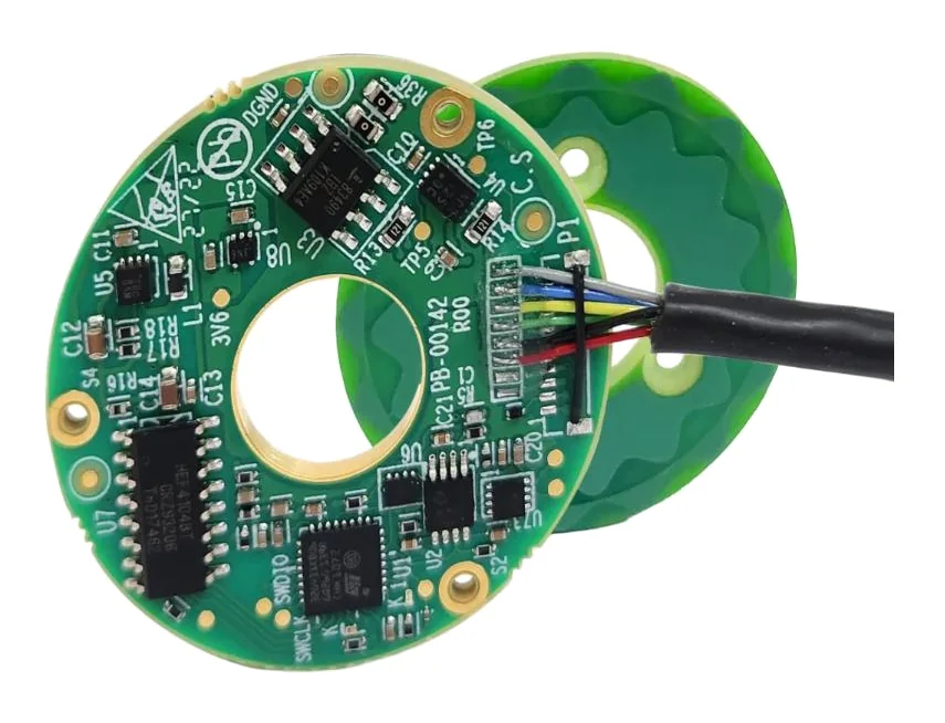
In short:Start from the accuracy you need at the load, not the resolution on the datasheet. Pick the sensing technology the environment allows (optical for the best accuracy in clean conditions, magnetic for dirt and cost, capacitive or inductive for hollow, thin, contamination-tolerant designs), choose a kit or housed format for your mechanics, then confirm the interface with the drive and that your mounting tolerances, especially eccentricity, fit the error budget.
The decisions, in order
An encoder tells the drive and controller where the axis is. Choosing one starts at the load and works back to the sensor:
- Requirement at the load: accuracy, repeatability and resolution in µm or arcsec, and where they are measured.
- Absolute or incremental, single-turn or multi-turn. Our absolute vs incremental encoder guide covers this choice in depth.
- Rotary or linear, and whether the encoder measures the motor or the load.
- Sensing technology: optical, magnetic, capacitive or inductive.
- Format: housed with bearings, kit or ring, or open read head and scale.
- Interface to the drive or controller.
- Environment: contamination, temperature, shock, vibration, magnetic fields, IP rating.
- Mounting tolerances: eccentricity, air gap and alignment, and whether your mechanics can hold them.
Step 1: turn the requirement into an error budget
Convert the tolerance at the tool or load into the encoder’s units. For a rotary axis, linear error at radius r is angle (rad) × r, and 1 arcsec = 4.85 × 10⁻⁶ rad. At 200 mm radius, 1 arcsec is about 1 µm.
Then separate three numbers, because suppliers quote them separately:
- Resolution: the smallest step reported. For a rotary encoder with n bits, one count is 1,296,000 / 2ⁿ arcsec: 17 bits is about 9.9 arcsec, 20 bits about 1.2 arcsec, 23 bits about 0.15 arcsec.
- Accuracy: the worst difference between reported and true position over the whole travel, after installation.
- Repeatability: the spread when returning to the same position, usually much smaller than accuracy.
These can be far apart. A Celera Motion IncOder guide lists the 58 mm unit at up to 17-bit resolution with a static accuracy of ≤150 arcsec over 360° (Celera Motion). That is ideal for a servo velocity loop and a repeatable indexer, but not for a pointing axis that needs 30 arcsec absolute.
Rules of thumb: resolution at least four to ten times finer than the accuracy you need; much finer than that on direct-drive axes, where the velocity loop differentiates the encoder signal and coarse counts become audible noise and velocity ripple. If the task repeats to taught positions, budget for repeatability; if it must hit coordinates it has never visited (pointing, metrology, CNC), budget for accuracy.
Step 2: motor-side or load-side, rotary or linear
A motor encoder behind a gearbox gains resolution from the ratio, but it cannot see backlash, wind-up or transmission error. Harmonic Drive LLC notes, for example, that in a geared actuator most output error comes from the gear’s transmission error because motor-side error is divided by the ratio (Harmonic Drive LLC). If the load must be accurate, measure the load:
- Rotary at the output (a ring or hollow encoder on the joint or table)
- Linear on the carriage (a scale and read head), removing screw lead error, thermal growth of the screw and belt stretch
Linear encoders come as tapes, bars or rigid scales. Magnetic tape suits long travel and dirt; Bogen’s LMSA absolute scale runs to 32.7 m. Capacitive linear systems such as Kappasense FREEe offer ±5 µm accuracy with a passive read head and no moving cable on the head.
Step 3: choose the sensing technology
| Technology | Strengths | Limits | Typical uses |
|---|---|---|---|
| Optical (glass or steel scale) | Highest resolution and accuracy; Renishaw’s REXA30 reaches ±1 arcsec installed on rings ≥100 mm with two read heads | Needs a clean optical path; tight ride-height tolerance (0.8 ± 0.15 mm for REXA30); higher current draw | Metrology, semiconductor stages, high-end rotary tables |
| Magnetic (ring or tape with Hall or MR head) | Rugged, tolerant of oil, dirt and moisture, low cost, simple | Lower accuracy; affected by external magnetic fields; magnetisation and eccentricity errors on small rings | Motor feedback, AGVs, long linear axes, harsh machinery |
| Capacitive | Thin, light, hollow; tolerant of contamination; immune to magnetic fields; low power | Accuracy below the best optical systems; needs a controlled air gap and good cable shielding | Robot joints, gimbals, defence and aerospace axes |
| Inductive | Very tolerant of dirt, water and mounting error; ignores static magnetic fields; wide temperature ranges | Modest accuracy on small sizes (Celera quotes <353 arcsec for the 37 mm IncOder); best results on larger diameters | Harsh outdoor, subsea, defence, large-bore axes |
Sources: optical figures from Renishaw; contamination and magnetic susceptibility comparison from Design World; inductive immunity from Celera Motion, which states IncOders are unaffected by humidity, condensation, dirt, dust, oil, mud or sand and that DC magnetic fields are not a concern because the sensor works with AC fields at a specific frequency; capacitive features from Netzer.
Magnetic fields matter. Motor magnets, brakes and high-current cables near a magnetic encoder can corrupt its reading. If a magnetic encoder must sit beside a brake or motor end-turns, ask for shielding guidance or choose capacitive or inductive.
Step 4: housed, kit or open read head
- Housed (shafted or hollow-shaft) encoders have their own bearings. They are the simplest to fit but add a coupling or a flexible tether, and the coupling’s error goes into your measurement.
- Kit and ring encoders mount the rotor directly on your shaft and the stator on your housing. They allow large bores, thin profiles and low mass, but your bearings and machining set the accuracy.
- Open read heads with scales or rings give the most freedom, and the most responsibility for alignment.
Step 5: interface
Match the drive’s native input before anything else:
- A/B/Z quadrature (RS422, TTL or HTL): incremental, universal, needs homing.
- Sine/cosine 1 Vpp: analogue, interpolated by the drive; resolution depends on the drive.
- BiSS-C and SSI: open absolute serial protocols, widely supported.
- Proprietary serial (EnDat, Nikon A, Tamagawa and others): fine if your drive supports them.
- SPI or asynchronous serial: common on OEM boards and embedded controllers.
Check maximum cable length at the clock rate you need, update rate for the control loop, supply voltage range, and how multi-turn data is kept (battery, energy harvesting, or gear-based).
Step 6: environment
List temperature range, shock and vibration levels, IP rating, washdown chemicals, vacuum and radiation where relevant. Temperature affects more than survival: steel and aluminium grow at different rates, so a scale and a housing of different materials shift relative to each other. Renishaw, for example, quotes a thermal expansion coefficient of 15.5 µm/m/°C for its REXA30 ring (Renishaw).
Step 7: mounting tolerances and eccentricity
On ring encoders, eccentricity between the ring and the rotation axis is usually the biggest installation error. RLS gives it as:
E = ±0.114 × e / D (degrees), with e in µm and D in mm (RLS).
| Ring diameter | e = 5 µm | e = 10 µm | e = 20 µm |
|---|---|---|---|
| 50 mm | ±41 arcsec | ±82 arcsec | ±164 arcsec |
| 100 mm | ±21 arcsec | ±41 arcsec | ±82 arcsec |
| 200 mm | ±10 arcsec | ±21 arcsec | ±41 arcsec |
Ways to deal with it:
- Two read heads 180° apart, which cancel eccentricity. Renishaw states that eccentricity is the only significant installation error on REXA30 and that two read heads remove it (Renishaw).
- Whole-circumference sensing: Netzer’s capacitive encoders scan and average the full rotor circumference; their VLX range accepts eccentricity plus air-gap error up to ±0.3 mm, and the DS range ±0.1 mm (Netzer).
- Calibration after installation, mapping the installed error and correcting it in the drive or controller.
Air gap matters too. Celera Motion notes that widening the IncOder gap tolerance from ±0.35 mm to ±0.50 mm doubles the guaranteed non-linearity (Celera Motion).
Worked example: outdoor pan axis on a sensor positioner
Requirement: A direct-drive pan axis on an outdoor sensor positioner. Absolute pointing accuracy ±0.02° (±72 arcsec). −40 to +70 °C. A 60 mm bore for slip ring wiring. Holding brake near the encoder. Drive reads BiSS-C. Must know its position at power-up.
Absolute, single-turn: the pan axis needs position at start-up; single-turn is enough if the controller tracks cable wrap or a slip ring allows unlimited rotation.
Resolution: with accuracy at 72 arcsec and a direct-drive velocity loop, aim well finer: 19 bits (about 2.5 arcsec) or more.
Budget for installation error: allow half the budget, ±36 arcsec, for eccentricity. With a ring of about 100 mm, the RLS formula allows e = 0.01° × 100 / 0.114 ≈ 9 µm. Holding 9 µm across −40 to +70 °C on an outdoor bearing assembly is hard.
Technology:
- Optical ring: accurate, but outdoor condensation and dust mean a sealed housing, and the eccentricity problem still needs two heads.
- Magnetic ring: rugged, but small-ring accuracy classes and the brake’s field make the budget tight. Bogen’s RMSI rings, for example, default to a 600 arcsec class, with tighter classes to ±25 arcsec depending on diameter.
- Capacitive or inductive hollow encoder: tolerant of mounting error, contamination and magnetic fields, with ranges rated to −55 °C (Netzer VLS) or −60 °C (Novanta Midi Ultra IncOder options).
Choice: a hollow-shaft capacitive or inductive absolute encoder with BiSS-C, such as Netzer VLS or a Novanta Midi Ultra IncOder in a size with a bore over 60 mm, with its published accuracy checked against 72 arcsec less the other errors (bearing wobble, structure deflection, thermal).
Products in our range to consider
- Netzer VLX: ultra-thin hollow-shaft capacitive absolute encoder, up to 23 bits, SSI or BiSS-C.
- Netzer VLS: hollow-shaft capacitive encoder rated −55 to +125 °C, bores to 171.4 mm.
- Netzer VLM: multi-turn absolute hollow-shaft capacitive encoder that keeps position through power loss.
- Netzer DS: encapsulated, factory-assembled VLX for easier installation, 16–130 mm OD.
- Novanta Midi Ultra IncOder: inductive absolute encoder, 75–300 mm OD, up to 22 bits, accuracy ≤19 arcsec depending on size.
- Novanta Mini Ultra IncOder: 37 and 58 mm inductive absolute encoder, IP67 possible, −60 to +105 °C.
- Bogen AKS16: absolute magnetic sensing head for linear and rotary scales, BiSS-C, SSI or ABZ.
- Bogen RMSI: incremental magnetic ring scales, radial or axial, high-temperature magnet options.
- Bogen LMSA: absolute two-track magnetic linear scale up to 32.7 m, no homing at power-up.
- Kappasense FREEe: capacitive absolute linear encoder, ±5 µm accuracy, passive 3 g read head.
What else the build needs
- Drive or controller that reads the protocol natively. See servo drives and motion controllers.
- Motor and its commutation feedback. See servo and stepper motors and frameless torque motors.
- Bearings and structure stiff and accurate enough to hold the encoder’s mounting tolerance.
- Gearing, if any, and a decision on motor-side vs load-side feedback. See gearboxes.
- Cabling: shielded, twisted-pair, rated for flex, with correct termination for RS422 lines.
- Slip ring if feedback must cross continuous rotation; choose data-rated circuits. See how to select a slip ring.
Things that catch engineers out
- Buying resolution for an accuracy problem. More bits do not remove eccentricity, magnetisation error or wind-up.
- Measuring the motor when the load matters. Gear and screw errors are invisible to a motor encoder.
- Eccentricity on small rings. A few microns cost tens of arcseconds.
- Magnetic encoders beside brakes or motors. Stray fields corrupt readings.
- Thermal mismatch between scale and machine on linear axes.
- Drive protocol assumed, not checked. Confirm the exact protocol variant, clock rate and multi-turn format.
- Long unshielded cables. Noise on serial or quadrature lines shows up as lost counts or communication faults.
Checklist
Send these to our engineers, or enter them in the spec builder:
- Rotary or linear; motor-side or load-side
- Accuracy, repeatability and resolution needed, and the radius or length they apply to
- Absolute or incremental; single-turn or multi-turn
- Shaft, bore and envelope (OD, thickness, mass)
- Interface and drive or controller model
- Maximum speed (rpm or m/s) and update rate
- Temperature range, IP rating, contamination, shock and vibration
- Nearby magnetic sources (brakes, motors, high-current cables)
- Mounting tolerances your mechanics can hold (eccentricity, air gap, tilt)
- Cable length and connector
- Quantities and timing
For the wider family, see our encoders overview.
Frequently asked questions
What is the difference between encoder resolution and accuracy?
Resolution is the smallest step the encoder reports. Accuracy is how far the reported position can be from the true position anywhere in the travel. They are often far apart: one Celera Motion IncOder guide lists 17-bit resolution (about 9.9 arcsec per count) for a 58 mm unit with a static accuracy of ≤150 arcsec. Repeatability, returning to the same reading, is usually much better than accuracy.
Which encoder technology is best in dirty environments?
Magnetic, capacitive and inductive encoders all tolerate dust, oil and moisture far better than optical encoders, which need a clear optical path. Inductive designs also ignore static magnetic fields. Celera Motion states its IncOder inductive encoders are unaffected by dirt, oil, mud and condensation. Optical encoders are still used in dirty machines, but sealed and housed, or with a protected scale.
How much does eccentricity affect a ring encoder?
A great deal on small rings. RLS gives the eccentricity error of a ring as ±0.114 × e / D degrees, with e in µm and D in mm. On a 50 mm ring, 10 µm of eccentricity gives about ±0.023°, or ±82 arcsec. Dual read heads cancel it, and whole-circumference capacitive or inductive designs reduce it.
Should I choose a kit encoder or a housed encoder?
Choose a housed encoder with its own bearings when you want it to bolt to a shaft and work, and can couple it to the axis without much error. Choose a kit or ring encoder when you need a large hollow bore, a thin profile, low mass or the encoder must sit right at the joint. Kits give better system accuracy only when you can hold their mounting tolerances.
What interface should my encoder use?
Use the one your drive or controller reads natively. BiSS-C and SSI are common open absolute serial protocols, A/B/Z quadrature for incremental feedback, and sine/cosine analogue where the drive interpolates. Vendor protocols such as EnDat or Nikon A tie you to compatible drives. Confirm cable length, update rate and multi-turn support before ordering.
What is a capacitive encoder?
It senses angle or position from changes in capacitance between patterned electrodes on a rotor and stator, with no optics and no magnets. Netzer's Electric Encoder, for example, scans the full rotor circumference continuously and averages the signals, and its VLX range accepts eccentricity plus air-gap error of up to ±0.3 mm. The result is a thin, light, hollow-shaft encoder tolerant of contamination.
Sources
- RLS: Accuracy of the ring encoder
- Renishaw: REXA30 absolute angle encoder data sheet
- Celera Motion (Zettlex): IncOder product guide MINI, Rev 4.11.6 (Kollmorgen copy)
- Netzer Precision: Product catalogue 2025 (distributor copy)
- Design World (J. Smoot, CUI): Capacitive, magnetic and optical encoders, comparing the technologies
- Harmonic Drive LLC: FHA-Mini 24 VDC actuator catalogue (positioning accuracy definition)
Figures are summarised from the sources above and from manufacturers' published data on the date shown. Always confirm against the current datasheet for your exact part.