
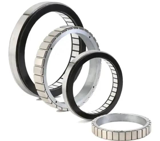
Establish the complete assembly
A frameless kit normally contains rotor and stator elements rather than a finished housed motor. Kollmorgen’s published explanation describes the housing, bearings, shaft and feedback as parts integrated into the machine. This changes the information needed for selection: a torque figure alone is not enough.
Record the available inner and outer diameter, axial length and required clear bore. Include bearings, seals, encoder, rotor support and cable routing in the envelope. Identify whether the motor drives the load directly or through gearing.
Checklist
| Area | Question to resolve |
|---|---|
| Bearings | What supports radial, axial and overturning loads? |
| Alignment | How are air gap, concentricity and runout maintained? |
| Rotor retention | What locates and retains the rotor throughout the duty? |
| Stator mounting | What installation method and tolerances does the manufacturer specify? |
| Heat removal | What mounting structure, ambient and cooling conditions apply? |
| Feedback | What position and commutation information does the drive need? |
| Cables and sealing | How are exits, strain relief and environmental protection achieved? |
Use the selected manufacturer’s installation instructions for materials, bonding, fits and assembly methods. This checklist does not provide manufacturing tolerances or a substitute installation procedure.
Check the installed thermal conditions
A motor’s continuous torque depends on stated thermal assumptions. The surrounding structure and heat path can change the available continuous performance. Describe the actual mounting material, nearby heat sources, cooling and duty rather than borrowing the performance of a different housed assembly.
Rotor, bearings, feedback and gearing can also be affected by the temperatures in the joint. Discuss the complete arrangement with the product supplier and responsible designer. Do not assume a motor kit has a complete-joint IP rating or environmental approval.
Match drive and feedback requirements
The drive needs a supported motor winding and suitable feedback or commutation information. Check supply, current conventions, motor constants, sensor signals and the exact encoder interface. Mechanical integration and electrical compatibility should be reviewed together.
For a gimbal or robot joint, record the load inertia, gravity torque, acceleration, smoothness, holding duty and reversal requirements. Include the location at which position performance must be measured. The gimbal application guide illustrates the wider component discussion.
Request a defined integration review
Send a section drawing or sketch, motion profile, envelope, cooling assumptions and intended drive. State prototype and expected production quantities. We can discuss frameless ranges and custom options, with the exact product capability and scope of engineering support confirmed for the enquiry.
Sources
Figures are summarised from the sources above and from manufacturers' published data on the date shown. Always confirm against the current datasheet for your exact part.