
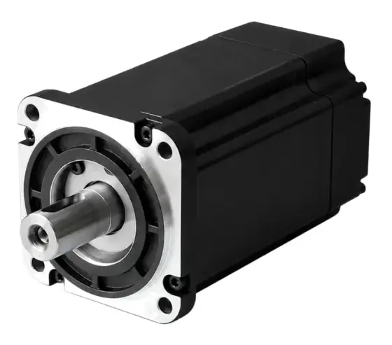
In short:Decide brushed or brushless first, mainly on required life and whether you can fit a controller, then choose the rotor type (iron-core, coreless or slotless) for inertia, smoothness and cost. Size from the operating point: pick a gearhead ratio that puts the motor in its efficient speed range, check torque against the continuous rating, and choose the winding so the speed-torque line passes through that point at your 12, 24 or 48 V supply.
Small DC motors drive pumps, valves, locks, mobility products, instruments and battery tools, often at volumes where the motor choice sets both product cost and warranty returns. Selection is a sequence: commutation type, rotor construction, operating point, gearing, winding, then options. This guide covers permanent-magnet DC motors up to a few hundred watts; for servo-grade brushless motors with encoders and drives, see servo vs stepper and how to select a servo drive.
Step 1: Brushed or brushless
| Brushed DC | Brushless DC (BLDC) | |
|---|---|---|
| Electronics | Runs from DC or simple PWM; reverse by polarity | Needs a controller to commutate |
| Life | Limited by brush and commutator wear | Limited mainly by bearings |
| Speed | Limited by commutation | Very high speeds possible |
| Electrical noise | Brush arcing generates EMI | Lower; no commutator arcing |
| Cost | Lowest system cost | Higher, but cheaper at long life |
| Sealing | Brush dust inside the motor | Can be fully sealed |
maxon puts brushed motor life at roughly 1,000 to 3,000 hours under average conditions, over 20,000 hours in favourable conditions and under 100 hours in rare extreme ones (maxon). Brushless motors operated within specification should reach around 20,000 hours, with bearings as the main limit (Eureka).
Rule of thumb: multiply operating hours per day by days per year by product life. If the answer is well above a few thousand hours, start with brushless or plan brush replacement into the service schedule.
Step 2: Choose the rotor construction
- Iron-core brushed (PMDC): a wound, laminated armature. Robust, high thermal capacity, low cost, but has cogging and higher rotor inertia. The workhorse for geared drives in gates, hoists, mobility and traction.
- Coreless (ironless) brushed: a self-supporting copper winding with no iron in the rotor. No magnetic cogging, low inductance, low inertia for fast acceleration and low EMI (maxon). Ideal for battery instruments, medical pumps and small precision axes. Lower thermal mass means short overloads heat the winding fast.
- Slotted brushless: windings in a slotted stator. Good torque density; some cogging.
- Slotless brushless: windings in an air gap with no stator teeth. No cogging and very high speeds, suiting blowers, surgical tools, pumps and smooth low-speed motion.
- Outrunner brushless: rotating outer magnet bell. High torque for its size at low speed; used for fans, propellers and gimbals. See how to select a drone motor.
Step 3: Define the operating point and duty
Write down, at the load:
- Torque and speed at the main operating point, and any peak (start-up, jam, end-stop)
- Duty: continuous, intermittent (on-time and off-time), start-stop or reversing
- Ambient temperature and how heat leaves the motor (mounting plate, airflow, sealed enclosure)
- Supply: battery chemistry and voltage range, or regulated DC
For intermittent duty, compute RMS torque over the cycle and compare that with the continuous rating; check peak torque against the short-term limit.
Step 4: Choose the gearhead ratio
Small DC motors produce useful power at high speed: maxon gives optimal operating speeds of 4,000 to 9,000 rpm depending on motor size (maxon). Most applications need far less speed and far more torque, so a gearhead is normal.
- Ratio i ≈ motor target speed ÷ load speed, rounded to an available ratio
- Motor torque = load torque ÷ (i × η_gear)
- Planetary gearheads give the most torque in a round package; spur gearheads are cheaper and quieter at light load; worm gears give a right angle, high ratios and often a degree of self-locking, at lower efficiency.
Take gear efficiency from the gearhead datasheet for the number of stages; it falls with each stage. Check the gearhead’s continuous and intermittent output torque ratings separately from the motor.
Step 5: Check torque, speed and efficiency on the motor curve
The key relationships for a permanent-magnet DC motor (common engineering formulas):
- Torque constant and speed constant: kM (mNm/A) × kn (rpm/V) ≈ 30,000/π ≈ 9,549
- Current: I = M ÷ kM + I₀ (I₀ is the no-load current)
- Speed at load: n ≈ kn × U − (Δn/ΔM) × M
- Speed-torque gradient: Δn/ΔM ≈ (30,000/π) × R ÷ kM², in rpm/mNm. A smaller gradient means speed varies less with load.
- Stall (starting) current: I_A = U ÷ R
No-load speed and stall torque both scale with voltage (maxon), so changing voltage shifts the speed-torque line parallel to itself. The operating point must:
- Lie on that line at your supply voltage (or at the PWM duty you plan)
- Sit inside the continuous operating range, set by maximum continuous torque and maximum speed
- Ideally sit near the efficient region. maxon’s rule of thumb puts maximum efficiency at roughly one seventh of stall torque (maxon)
Step 6: Choose the winding for your 12, 24 or 48 V system
Most frame sizes come in several windings. A low-resistance, few-turn winding gives high kn (rpm per volt) and high starting current; a high-resistance winding gives the reverse (maxon). Choose the winding whose speed-torque line passes through your operating point at the supply voltage, with a little speed in hand for low battery voltage.
- 12 V: automotive and small battery products. Currents are high for a given power, so cable and connector losses matter.
- 24 V: the industrial standard; good component availability.
- 48 V: halves the current of 24 V for the same power, reducing cable size and I²R losses, while staying within extra-low-voltage design practice. Increasingly used in mobile robots and AGVs.
On battery systems, check the operating point at both the fully charged and the minimum voltage. Size the controller’s current limit against the stall current, not the running current.
Step 7: Choose brushes, encoder and options
Brushes. maxon’s guidance (maxon):
- Precious metal brushes: smaller motors, continuous running at low current (below about 50% of maximum continuous current), quieter, lower cost; maximum winding temperature 85 °C in that design.
- Graphite brushes: higher current (about 50–80% of maximum continuous), start-stop and reversing duty, peak currents; up to 125 °C winding temperature. More sensitive to atmosphere and humidity extremes.
Feedback. Add an encoder when you need speed regulation under varying load, position control or stall detection. Magnetic encoders are cheap and robust; optical encoders give higher resolution. A tachogenerator remains an option on brushed servo motors driven by analogue drives. See encoders.
Other options: a holding brake for lifting or parking, shaft and flange customisation, connector or flying leads, and EMC suppression components on brushed motors.
Worked example: a 24 V peristaltic pump drive
Requirement: 0.6 Nm at 100 rpm at the pump shaft, continuous, 24 V DC regulated supply, 8 hours a day, 250 days a year.
Gearhead: target motor speed about 4,300 rpm, inside the 4,000–9,000 rpm band. Ratio 4,300 ÷ 100 = 43:1. Assume a planetary gearhead at 0.72 efficiency for this number of stages (use the real datasheet figure).
- Motor torque = 0.6 ÷ (43 × 0.72) ≈ 0.0194 Nm = 19.4 mNm
- Output power ≈ 0.0194 × 4,300 × 2π ÷ 60 ≈ 8.7 W
Motor and winding. Take a candidate coreless motor frame whose speed-torque gradient is about 30 rpm/mNm (an assumed datasheet value), with a continuous torque comfortably above 19.4 mNm.
- Voltage needed at the load: U = (n + gradient × M) ÷ kn
- For a 24 V supply: kn = (4,300 + 30 × 19.4) ÷ 24 ≈ 4,880 ÷ 24 ≈ 203 rpm/V
- Corresponding torque constant: kM ≈ 9,549 ÷ 203 ≈ 47 mNm/A
- Running current: 19.4 ÷ 47 + about 0.03 A no-load ≈ 0.44 A
- Electrical input ≈ 24 × 0.44 ≈ 10.6 W, so motor efficiency ≈ 8.7 ÷ 10.6 ≈ 82%
- Winding resistance implied by the gradient: R ≈ gradient × kM² ÷ 9,549 ≈ 30 × 47² ÷ 9,549 ≈ 7 Ω, so starting current ≈ 24 ÷ 7 ≈ 3.4 A. Set the controller’s current limit with that in mind.
Pick the nearest catalogue winding to 203 rpm/V; a slightly higher kn plus PWM speed control gives headroom for tubing wear.
Brushes and life. Running current is low relative to the motor’s continuous rating, so precious metal brushes suit the duty. But 8 × 250 = 2,000 hours a year. Against a typical 1,000–3,000 hour brushed life, the motor could need replacing within a year or two. If the product is meant to last five years without service, a slotless brushless motor with a planetary gearhead is the better choice, at the cost of a small controller.
Products in our range to consider
- D-Series DC coreless motors: brushed coreless motors in 13–40 mm frames at 3–48 V DC, cog-free and low inertia, up to 0.187 Nm continuous, with encoder and gearhead options.
- DINGS ZYT brushed DC motors: small brushed motors from 8 to 80 mm at 12/24 V, with encoder, brake and planetary gearbox options to ratios as high as 1,526:1.
- ZYT PMDC brushed motors: iron-core permanent-magnet motors 30–110 mm at 12–48 V up to about 1.5 kW, with worm gearbox and 12/24 V parking brake options for traction and lifting.
- BDS Series DC brushed servomotors: 82 and 102 mm brushed servo motors with a 9.5 V/krpm tachogenerator, 0.5–4.5 Nm continuous stall torque and peaks to 22 Nm.
- DINGS ZWWC slotless brushless motors: 10–42 mm slotless BLDC motors at 12–48 V running to about 50,000 rpm with no cogging, with Hall or encoder and gearbox options.
- Kinco SMC low-voltage DC servo motors: 24–48 V brushless servo motors from 50 W to 3 kW, IP65, with incremental or absolute encoders.
- Leadshine ELVM low-voltage DC servo motors: 24–60 V PMSM motors from a 25 mm, 33 W unit to a 130 mm, 2 kW unit, up to 6.4 Nm rated.
- Leadshine ELD3 miniature DC servo drives: 24–70 V DC drives from 50 to 750 W that also run brushed and slotless motors.
What else the build needs
- Gearhead: planetary, spur or worm, matched for ratio, torque and backlash. See gearboxes.
- Controller or drive: H-bridge PWM for brushed motors, a BLDC controller for brushless, or a servo drive for position control. See servo drives.
- Encoder or Hall sensors for speed or position feedback. See encoders.
- Brake for lifting, parking or holding against back-driving.
- Power supply or battery sized for stall current at start-up.
- EMC suppression (capacitors, chokes) on brushed motors.
- Linear conversion if the output is linear: a lead screw or a complete actuator. See linear actuators and how to size a linear actuator.
- Slip ring if power must cross a continuously rotating joint. See slip rings.
Things that catch engineers out
- Sizing at stall or no-load figures rather than at the operating point on the speed-torque line.
- Forgetting gearhead efficiency, which falls with every stage and can take a large share of the torque in a multi-stage box.
- Ignoring low battery voltage, which shifts the speed-torque line down and leaves the product slow at end of charge.
- Overloading a coreless motor for “just a few seconds” and damaging the winding, because its thermal time constant is short.
- Brushed motors in long-life products without a service plan for brush wear.
- Precious metal brushes on start-stop or high-current duty, which shortens their life.
- No current limit in the controller, so a jammed mechanism draws full stall current.
- Graphite brushes in a vacuum or very dry atmosphere, where the commutator film does not form.
Checklist
Send these to our engineers, or enter them in the spec builder:
- Output torque and speed at the operating point, and any peak or stall condition
- Duty cycle: continuous, intermittent, start-stop, reversing
- Required life in hours, and whether service is possible
- Supply: nominal voltage and range (battery minimum and maximum)
- Space envelope: diameter, length, shaft and flange
- Gearhead type and ratio if known, and backlash limit
- Feedback needed: none, Halls, encoder resolution, tachogenerator
- Brake, connector and EMC requirements
- Ambient temperature, sealing, noise limits
- Annual volume and target cost
Frequently asked questions
Should I choose a brushed or brushless DC motor?
Choose brushed when life requirements are modest, cost matters and you want to run directly from a DC supply or simple PWM. Choose brushless when you need long life, high speed, low electrical noise or a sealed motor, and can fit a controller. Brushed motors typically last 1,000 to 3,000 hours under average conditions; brushless designs are usually limited mainly by their bearings, often around 20,000 hours.
What is a coreless DC motor?
A coreless or ironless motor has a self-supporting copper winding with no iron lamination stack in the rotor. That removes cogging, gives very low rotor inertia for fast acceleration, low inductance and low electromagnetic interference. It suits battery-powered instruments, medical pumps and small precision axes. The trade-off is lower thermal capacity, so short overloads heat the winding quickly.
How do I read a DC motor speed-torque line?
At constant voltage a DC motor's speed falls linearly as load torque rises, from no-load speed to zero at stall torque. The slope is the speed-torque gradient; a smaller gradient means speed varies less with load. No-load speed and stall torque both scale with voltage, so the line shifts in parallel. Your operating point must lie on the line at your supply voltage and inside the continuous range.
What is the torque constant of a DC motor?
The torque constant, kM, is the torque produced per amp of winding current, in mNm/A. It is tied to the speed constant kn in rpm/V: kM multiplied by kn is about 9,549 in those units. A high-kM winding gives more torque per amp and less speed per volt. Choose the winding that reaches your speed at your supply voltage.
Where is a DC motor most efficient?
Efficiency peaks at fairly light load. maxon's rule of thumb is that maximum efficiency occurs at roughly one seventh of the stall torque. In practice, size so the continuous operating point sits between that and the motor's rated torque, rather than near stall, and use a gearhead to move the motor into its efficient speed range.
Graphite or precious metal brushes?
Precious metal brushes suit small motors running continuously at low current, typically below half the motor's maximum continuous current, and are quieter. Graphite brushes suit higher currents, frequent start-stop and reversing duty and larger motors, and tolerate peak currents better. maxon notes graphite brushes are more sensitive to atmosphere, temperature and humidity extremes.
Sources
- maxon: Properties of brushed DC motor commutation systems (graphite vs precious metal brushes)
- maxon: DC motor technology, short and to the point (2023)
- maxon: Key information, DC and EC motors (2009 catalogue section)
- Eureka magazine: Choosing a brushed or brushless DC motor
Figures are summarised from the sources above and from manufacturers' published data on the date shown. Always confirm against the current datasheet for your exact part.