
Three requirements that answer different questions
| Term | Practical question |
|---|---|
| Resolution | How small an increment can the reported position represent? |
| Accuracy | How close is reported position to the true position over the working range? |
| Repeatability | How consistently does the measurement or mechanism return under defined conditions? |
An encoder can produce a fine digital increment while its installed accuracy is limited by scale error, mounting or mechanical movement. Renishaw’s encoder guidance distinguishes these characteristics and explains the importance of the complete measurement arrangement.
An illustrative bit-count calculation
For a single-turn digital output with 20 bits, one revolution is represented by 1,048,576 increments. Dividing 360 degrees by that number gives approximately 0.000343 degrees per increment, or about 1.24 arcseconds.
That number is the nominal angular increment, not a statement that the machine is accurate to 1.24 arcseconds. It also does not establish noise, latency, cyclic error or repeatability. This is a mathematical worked example rather than a tested encoder or customer result.
Where the encoder is mounted matters
A motor-mounted encoder measures the motor. A gearbox, screw, coupling or flexible structure between it and the working point can introduce movement or error that the encoder does not observe directly. Discuss a load-side measurement when performance must be established at the table, tool or sample.
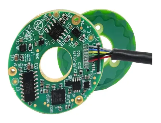
For ring and readhead arrangements, record mounting tolerances, eccentricity, runout, tilt, temperature and installation access. The actual manufacturer’s installation requirements take precedence over a generic guide. A component’s headline accuracy is not automatically the installed system accuracy.
Specify the operating conditions
State whether accuracy is required across the whole travel or only within a local working area. Explain reversal, temperature changes, speed and vibration. Include whether the application scans while moving or waits to settle before measurement.
The electrical interface must also suit the controller or drive. More bits can increase the amount of data to transfer, but the practical update behaviour depends on the exact device and interface implementation. Single-turn and multi-turn absolute requirements should be identified separately.
Prepare an encoder enquiry
Send the required tolerance at the working point, measurement range, speed, available envelope, shaft or bore and receiving controller. Include the environment and the intended mounting. Browse encoders or the hollow-shaft selection guide to identify relevant families, then ask for an exact-configuration review.
Sources
Figures are summarised from the sources above and from manufacturers' published data on the date shown. Always confirm against the current datasheet for your exact part.