
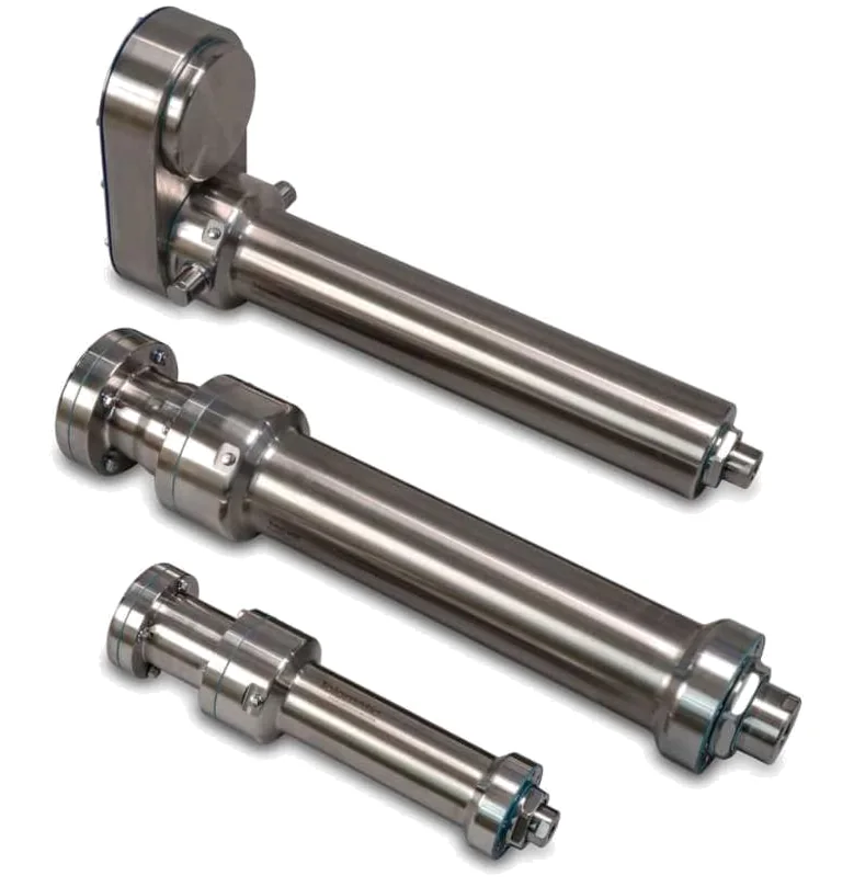
In short:Most hydraulic cylinders up to roughly 50 tonnes can be replaced by a servo-driven roller screw or ball screw actuator, provided you size it on the force the machine actually needs across the stroke, not the cylinder's theoretical maximum. Hydraulics still wins for the very highest forces, severe shock and long stall holds with no power.
Hydraulic vs electric actuators: what actually changes
A hydraulic cylinder turns pressure into force through a piston area. An electric actuator turns motor torque into force through a screw. That one difference drives everything else in a conversion: how force is controlled, how loads are held, how the axis survives impact, and how life is calculated.
The case for converting is usually a mix of energy, cleanliness and control. Tolomatic’s sizing guide puts hydraulic systems at only 40–55% efficient at converting electrical power to motion, against typically 75–80% for electric systems (Tolomatic). Add the power unit that runs to keep the circuit pressurised even when nothing moves, oil changes, filters and leak clean-up, and the running-cost argument is usually clear. On the control side, a servo-driven screw gives you programmable position, speed and force on every stroke, with feedback for process monitoring, without proportional valves.
The trade-offs are real, though. A screw has a finite calculated life, it does not like hard impacts, and it will back-drive unless you hold it.
| Factor | Hydraulic cylinder | Electric screw actuator |
|---|---|---|
| Force range | Very high; compact for its force | Up to roughly 50 tonnes is practical; above that, screw and motor sizes become the limit (Power & Motion) |
| System efficiency | About 40–55% | About 75–80% |
| Energy at rest | Power unit maintains pressure | Little to none (brake holds) |
| Position and force control | Needs servo or proportional valves and sensors | Built in via servo drive and encoder |
| Holding with power off | Check valves or counterbalance valves | Requires a spring-applied brake |
| Shock tolerance | Good; oil compresses and relief valves vent | Limited by screw static rating; roller screws better than ball screws |
| Maintenance | Oil, filters, hoses, seals, valves | Rod seal, lubrication, planned screw life |
| Temperature sensitivity | Oil viscosity changes; may need heating or cooling | Mainly motor thermal limits |
How to convert a cylinder spec to force
Start with the cylinder you have. Force is pressure times area:
- Extend: F = p × (π × D² / 4)
- Retract: F = p × (π × (D² − d²) / 4)
where p is pressure in pascals (1 bar = 10⁵ Pa), D is bore and d is rod diameter in metres, and F comes out in newtons.
That gives the theoretical force at the pressure you use. It is almost never the force you need. Tolomatic notes that hydraulic cylinders are often sized two or three times larger than required, and recommends finding the real peak by turning the pressure down until the cylinder can barely do the job, by fitting a load cell, or by back-calculating from servo current if the machine already has one (Tolomatic). A load cell is the best of these, because it gives the force at every point of the stroke, which you need for life calculations.
Speed is simpler: time the move (video with a scale in shot works) and divide distance by time for each segment of the cycle.
Roller screw vs ball screw for hydraulic replacement
Both are rolling-element screws, and both are efficient. Moog’s comparison table gives roller screws 75–90% and ball screws 85–95% efficiency, against around 40% for an Acme screw (Moog). The difference is in how load is carried.
A planetary roller screw transfers load through threaded rollers with many more contact points than a ball screw of the same size. Tolomatic and Moog both rate roller screws higher on dynamic load rating, life, shock resistance and acceleration, and lower on space for a given load (Tolomatic). In practice:
- Choose a roller screw for continuous high force, press-fit and forming, high duty cycles, any impact, or when the actuator has to fit the envelope of the cylinder it replaces.
- Choose a ball screw for moderate forces with smooth motion profiles, where cost matters and the calculated life is comfortable.
For more depth, see our guide to ball screw vs roller screw.
Life: why the force profile matters more than the peak
Screw life is estimated with the L10 formula, the distance 90% of a population of screws will reach:
L10 (revolutions) = (C / Fm)³ × 10⁶
where C is the screw’s dynamic load rating and Fm is the cubic mean force over the cycle:
Fm = ( Σ Fᵢ³ × sᵢ / Σ sᵢ )^(1/3)
with Fᵢ the force over travel distance sᵢ. Multiply revolutions by lead to get distance.
The cube is the point. Tolomatic warns that assuming peak force over the whole stroke will dramatically reduce estimated life (Tolomatic), which in turn pushes you to a larger, dearer actuator than you need. The worked example below shows by how much.
Holding loads and brakes
A hydraulic circuit can lock a cylinder with valves. A ball or roller screw is efficient enough that it will back-drive under load once the motor is de-energised. For any vertical axis, any axis holding a clamp or pre-load, or any axis that must not drift during an emergency stop, specify:
- A spring-applied, power-off brake on the motor or screw. Size its static holding torque above the back-driving torque at maximum load, with margin as a rule of thumb (1.5–2× is common practice), and check the motor’s brake can also stop the axis if your stop category requires it.
- Motor standstill torque that covers any hold under servo control. Holding full force with current produces heat with no movement, so check the motor’s stall rating, not just its rated torque.
- Where the risk assessment demands it, a second independent holding means, such as a rod lock.
Shock and side loads
Hydraulic oil compresses and a relief valve vents a pressure spike. A screw has nowhere to go: an impact goes straight into the rolling elements and the thrust bearings. Three practical rules:
- Keep the worst-case force, including impacts and jams, below the screw’s static load rating with a sensible safety factor. Use the servo drive’s force or torque limit to clip jam loads.
- Prefer roller screws where impacts are unavoidable; both Moog and Tolomatic rate them well above ball screws on impact resistance.
- Do not let the rod carry side loads. Cylinders often hide misalignment that a screw will not tolerate. Use a guided actuator, external linear guides or a clevis and rod-eye with spherical bearings.
Worked example: converting an 80 mm press cylinder
Existing cylinder: 80 mm bore, 45 mm rod, 300 mm stroke, system pressure set at 160 bar.
Theoretical force:
- Extend area = π × 0.080² / 4 = 5.03 × 10⁻³ m²
- Extend force = 160 × 10⁵ Pa × 5.03 × 10⁻³ m² = 80.4 kN
- Retract force = 160 × 10⁵ × π × (0.080² − 0.045²) / 4 = 55.0 kN
Measured requirement: the pressure is lowered until the press-fit just completes reliably, at 60 bar, so the real press force is 60 × 10⁵ × 5.03 × 10⁻³ = 30.2 kN. That is under 40% of the theoretical figure, consistent with the two-to-three-times oversizing Tolomatic describes.
Cycle (load cell and video):
- Approach: 250 mm at 100 mm/s, about 5 kN (tooling and friction)
- Press: 50 mm at 20 mm/s, 30.2 kN
- Retract: 300 mm at 100 mm/s, about 3 kN
- One cycle every 20 s, two shifts (16 hours a day)
Cubic mean force: Fm = ((5³ × 250 + 30.2³ × 50 + 3³ × 300) / 600)^(1/3) = 13.3 kN
Life check on a candidate screw. Take a roller screw with a dynamic load rating of 73.3 kN, which Tolomatic lists for a 20 mm diameter, 5 mm lead roller screw (Tolomatic):
- L10 = (73.3 / 13.3)³ × 10⁶ ≈ 167 × 10⁶ revolutions × 5 mm ≈ 837 km
- Each cycle travels 600 mm, so about 1.4 million cycles
- At 2,880 cycles a day, roughly 480 days
If you had wrongly assumed 30.2 kN over the whole stroke, the same screw calculates to (73.3 / 30.2)³ × 10⁶ ≈ 14 × 10⁶ revolutions, about 72 km or 42 days. The real profile gives more than ten times the life. For a production press, 480 days is still short, so the next step is a larger frame. Because life scales with the cube of C, a screw with about 1.5× the rating gives roughly 3.4× the life.
Motor torque at the screw (T = F × L / (2π × η), using η = 0.8):
- Press: 30,200 × 0.005 / (2π × 0.8) ≈ 30 Nm at 240 rpm
- Approach: 5,000 × 0.005 / (2π × 0.8) ≈ 5 Nm at 1,200 rpm
With a 2:1 belt or gearbox, that becomes about 15 Nm continuous during the press at 480 rpm, and 2,400 rpm on approach, which sits comfortably in a mid-size servo motor’s range. Calculate RMS torque over the cycle to size the motor thermally, and check the press hold time against the motor’s stall rating.
Holding: the press is vertical, so specify a power-off brake on the motor sized above the back-driving torque of the tooling weight, and confirm with the risk assessment whether a rod lock is also required.
Candidate products for this class of duty include roller screw actuators such as the Tolomatic RSA-HT and RSX, which Tolomatic now offers up to 294 kN (Tolomatic), and Exlar’s FTX and FTP press actuator. For lower-force mobile equipment on DC supplies, ball screw units like the Thomson Electrak XD are worth a look. Our general linear actuator sizing guide covers the motion profile side in more detail.
When hydraulics still wins
Converting is not always right. Keep hydraulics, or at least run the numbers very carefully, when:
- Force is extreme. Electric actuators reach around 50 tonnes in practice; hydraulic cylinders go further in a smaller envelope (Power & Motion).
- Impacts are severe and repeated, such as breakers, crushers or anything that currently relies on a relief valve to survive.
- Full force must be held for long periods with no power and a brake or mechanical lock is not acceptable.
- The machine already has hydraulic power (many mobile machines do) and electrical capacity is limited.
- The environment rules out motors, for example some hazardous areas or full immersion, unless suitably certified equipment is available.
Checklist
Send these to an engineer, or enter them in the spec builder, to get a meaningful proposal:
- Existing cylinder: bore, rod, stroke, mounting style and system pressure
- Measured force profile (load cell trace, or working pressure for each segment)
- Speed and distance for each segment of the cycle, plus dwell times
- Cycle rate, shifts per day and required life in years or cycles
- Orientation, and whether the load must be held with power off
- Any impact, jam or overload cases, and side loads on the rod
- Accuracy and repeatability needed at the end of stroke
- Supply available (mains AC, 24/48 V DC), controller and fieldbus
- Environment: temperature, washdown, IP rating, hazardous area
- Space envelope, and whether it must fit the existing cylinder mounts
Our specialist engineering and supply partners can then propose a screw type, frame size, motor and brake that fit the duty with documented life.
Frequently asked questions
How do I work out the force of my existing hydraulic cylinder?
Multiply pressure by piston area. For extension, area is pi times bore squared divided by four; for retraction, subtract the rod area. An 80 mm bore at 160 bar gives about 80 kN extending. That is the theoretical maximum at relief pressure, though. Measure the working pressure during the real cycle, or fit a load cell, to find the force the job actually needs before sizing the electric replacement.
Should I choose a roller screw or a ball screw for hydraulic replacement?
For forces above a few tens of kilonewtons, continuous duty, or any shock loading, a planetary roller screw is the usual choice because it carries more load in the same diameter and tolerates impact better. Ball screws are cheaper, slightly more efficient and perfectly adequate for moderate forces with smooth profiles. Compare L10 life for both on your real force profile rather than choosing on peak force alone.
Can an electric actuator hold a load with the power off?
Not by itself. Ball and roller screws are efficient enough to back-drive, so a vertical or pre-loaded axis will move when the motor is de-energised. Specify a spring-applied, power-off holding brake on the motor or screw, sized with margin over the back-driving torque, and check whether your risk assessment also needs a mechanical rod lock or a second brake.
Is an electric actuator more energy efficient than hydraulics?
Usually, by a wide margin. Tolomatic quotes hydraulic systems at roughly 40 to 55 percent efficient at turning electrical power into motion and electric actuator systems at about 75 to 80 percent. The bigger saving is often at rest: an electric axis draws little power when stationary, while a hydraulic power unit has to keep the system pressurised.
What maintenance does an electric actuator need compared with a hydraulic cylinder?
There is no oil, filters, hoses or valves to look after. The screw and thrust bearings are typically greased for life or re-greased at long intervals, and the rod seal is the main wear part. You will still need to plan for screw life, which is calculated from the force profile and distance travelled, and for the motor brake if one is fitted.
When should I keep hydraulics instead of converting?
Keep hydraulics when forces go well beyond what roller screws and servo motors can supply economically, when the actuator sees repeated hard impacts that a relief valve currently absorbs, when it must hold full force for long periods with no power, or when a mobile machine already has a hydraulic supply and electrical power is limited.
Sources
- Tolomatic: How to size hydraulic cylinders to electric actuators (9900-9239)
- Tolomatic: Roller screw technical overview
- Moog: Planetary roller screws catalogue
- Power & Motion: Why electric actuators are replacing hydraulics
- Tolomatic: RSX high-force actuator range expanded to 294 kN
Figures are summarised from the sources above and from manufacturers' published data on the date shown. Always confirm against the current datasheet for your exact part.