
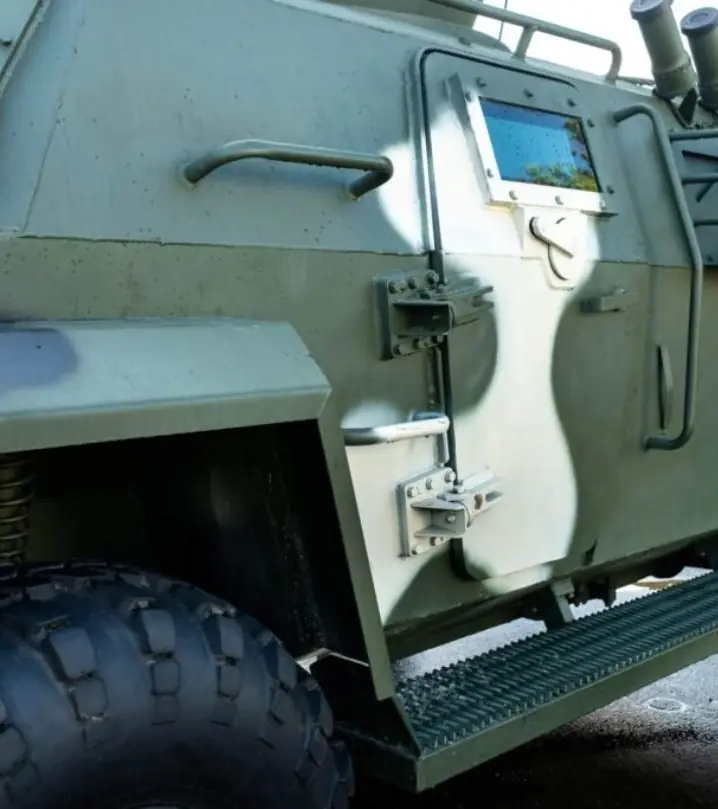
In short:A turret or remote weapon station is, at component level, a heavy two-axis positioner on a moving vehicle: a large-bore slip ring for power, video and Ethernet, torque motors with gearing or direct drive on azimuth and elevation, absolute encoders, and a servo drive running from 28 V vehicle power. Specify each for stiffness, shock and the vehicle environment, and leave system integration to the platform owner.
Typical requirements
| Turret slip ring power rings | 150–450 A per power ring at vehicle voltages (18–37 V DC) |
|---|---|
| Turret slip ring signal circuits | 12 to 238 circuits at 2–5 A |
| Turret slip ring data | MIL-STD-1553, RS-170 video, 100 Mbit and gigabit Ethernet |
| Turret drive performance (published example) | Under 0.3 mrad/s slow tracking; 1 rad/s maximum; 2 rad/s² acceleration |
| Stabilisation quality (published example) | 0.3 mrad (1σ) |
| Encoder shock rating (example) | 100 g for 11 ms (MIL-STD-810G) |
This page covers turrets and remote weapon stations strictly at component level: the slip rings, motors, gearing, encoders and drives that move a two-axis mount on a vehicle, vessel or fixed site. Whatever the payload, the motion problem is the same. A heavy, often unbalanced mass must slew quickly, hold a steady line of sight while the platform pitches and rolls, rotate continuously in azimuth, and survive shock, vibration, cold, heat, sand and water for years on a noisy vehicle supply.
Large-bore turret slip rings: power, video and Ethernet
Continuous azimuth rotation means everything crossing the turret ring goes through a slip ring, usually a through-bore unit sized to the ring opening. Moog’s published vehicular and turret slip rings illustrate what a remote weapon station slip ring has to carry:
| Model | Power rings | Signal circuits | Data and extras |
|---|---|---|---|
| AC3497 | 1 × 150 A | 12 × 5 A | Dual cam |
| VSR-4994 | 4 × 200 A, 24 V DC | 86 × 2–4 A | NBC air channel, 2 × MIL-STD-1553, 8 × RS-170 video |
| VSR-6057 | 2 × 250 A, 18–37 V DC | 238 × 2–4 A | High isolation concentric rings for EMI |
| VSR-6772 | 2 rings, 450 A and 75 A, 28 V DC | 150 | 100 Mbit Ethernet, resolver, pneumatic and hydraulic joint |
| VSR-7001 | 150 A, 120 A, 80 A, 13 A at 20–33 V DC | Twinax, coax | Gigabit Ethernet, RS-170 video, air channel, immersible to 1 m |
Source: Moog aerospace and defence slip ring catalogue. Moog lists gold-on-gold contacts, EMI shielding, full environmental sealing and military shock and vibration capability across the range.
What to state when specifying: bore and envelope, current per power ring and total, voltage, number and type of signal circuits, every data channel with protocol and rate, video format, any fluid or air passage, sealing (including immersion if the vehicle fords), and EMI isolation between power and signal. Read how to specify a slip ring, Ethernet through slip rings and our defence turret slip ring page, and see rugged military slip rings.
Torque motors and gearing for azimuth and elevation
Two drive architectures dominate.
| Architecture | How it works | Strengths | Watch out for |
|---|---|---|---|
| Geared turret drive | Servo motor and reduction drive a pinion on the ring gear | Compact motor, high output torque, easy manual backup | Backlash, gear compliance, wear; anti-backlash pinions or preload needed for stabilisation |
| Direct drive | Large frameless torque motor built into the ring or trunnion | No backlash, high stiffness, quiet, few wearing parts | Motor diameter and mass, heat in a sealed space, cost |
Kollmorgen describes its frameless KBM, TBM and RBE series for weapon stations; the RBE is a high-torque, low-speed pancake format that removes the shaft, bearings, endbells and couplings. For housed motors it offers a rugged servo range rated to MIL-STD-810E and sealed to IP67, with a stainless shaft and chemical agent-resistant paint. See frameless torque motors, frameless motor sizing and, for geared axes, harmonic vs planetary vs cycloidal and gearboxes.
How to size an axis:
- Calculate payload inertia about each axis, including cradle and cabling, and any static imbalance (elevation axes are rarely balanced).
- Set acceleration and speed from the slew requirement. As a published reference, one turret drive supplier quotes maximum speed of 1 rad/s and acceleration of 2 rad/s².
- Torque = inertia × acceleration + imbalance torque + friction + slip ring drag + margin for vehicle motion and wind.
- Check stiffness: the first structural resonance of motor, gearing and structure must sit well above the stabilisation loop bandwidth.
- Check thermal behaviour for the duty cycle inside a sealed housing.
Absolute encoders and feedback
Each axis needs an absolute encoder on the axis itself, so position is valid at power-up and no gear train sits between sensor and load. High-resolution ring encoders, capacitive and inductive kits, and resolvers all appear. Netzer’s encapsulated DS series, for example, offers up to 23-bit resolution with 100 g for 11 ms shock and 20–2,000 Hz vibration ratings under MIL-STD-810G. Large-bore inductive kits such as the Midi Ultra IncOder suit the hollow turret centre. Compare options in absolute vs incremental encoders.
Stabilisation loop requirements, in general terms
A stabilised mount uses gyroscopes to measure platform motion and drives the axes to cancel it. The published turret drive figures above include slow-speed tracking below 0.3 mrad/s and stabilisation of 0.3 mrad (1σ), with gyros added to an electric drive and RS-422, RS-485 or CAN interfaces. For component selection, the loop needs:
- High stiffness and low backlash between motor and load.
- Low torque ripple and cogging for smooth slow tracking.
- Fast current loop and adequate peak current in the servo drive.
- Low-noise, high-resolution feedback with low latency.
- Low, consistent slip ring drag torque that does not vary with temperature.
Shock, vibration, power and EMC
- Shock and vibration. Tracked and wheeled vehicles produce severe vibration, and the mount sees additional transient shock in use. MIL-STD-810H vibration (Method 514), shock (516) and gunfire shock (519) are common in tailored test programmes; UK programmes may use DEF STAN 00-35.
- Vehicle power. MIL-STD-1275E sets 20–33 V steady state and injected ±250 V spike tests on 28 V vehicles. Size drive input stages for surges and cranking dips.
- EMC. MIL-STD-461 or DEF STAN 59-411. High-current PWM drives inside a turret are a strong emission source; shielding and the slip ring’s isolation between power and signal rings matter.
- Sealing and NBC. Turret seals and slip ring air channels support NBC overpressure on many vehicles.
- Export control. Turret and weapon station components specially designed for military use are typically controlled; see the defence and security overview.
Typical pitfalls
- Under-sizing elevation torque by ignoring imbalance and vehicle pitch.
- Choosing a slip ring by circuit count alone without checking EMI isolation, data rates and drag torque.
- Placing the encoder on the motor of a geared axis and expecting the load to follow.
- Leaving vehicle supply transients to the system integrator.
- Ignoring heat in a sealed turret on a hot day.
Send axis inertias, speeds, bore, circuits and environment, and our specialist engineering and supply partners can propose slip rings, torque motors, gearing and feedback for the mount.
Standards to have in view
- MIL-STD-810H (environmental engineering and laboratory tests)
- MIL-STD-461H (control of electromagnetic interference; supersedes MIL-STD-461G)
- MIL-STD-1275E (28 V DC input power to utilisation equipment in military vehicles)
- DEF STAN 00-35 (environmental handbook for defence materiel)
- DEF STAN 59-411 (electromagnetic compatibility)
- MIL-STD-1553 (digital time division command/response multiplex data bus)
Which standards apply depends on the end product and its market. Your engineer will confirm what the component itself needs to meet.
Frequently asked questions
What does a remote weapon station slip ring carry?
Everything that must cross the continuously rotating azimuth axis: high-current DC power for drives and payloads, control and sensor signals, video, data bus and Ethernet, and on some designs an air channel for NBC overpressure or cooling. Moog's published turret slip rings combine power rings up to 450 A with up to 238 signal circuits, MIL-STD-1553, RS-170 video and gigabit Ethernet in through-bore, sealed and EMI-shielded housings.
Direct drive or geared turret drive?
Both are used. A pinion driving a large ring gear gives high torque from a compact motor, but backlash and gear compliance limit stabilisation bandwidth and need careful anti-backlash design. Direct-drive frameless torque motors remove backlash and offer high stiffness, at the cost of a large-diameter motor and more mass. The choice depends on payload inertia, required acceleration, stabilisation performance and space in the turret ring.
Which encoders suit turret azimuth and elevation axes?
Absolute encoders mounted directly on each axis, so position is known at power-up without homing and no gearing sits between sensor and load. Large-bore ring encoders, capacitive or inductive kits, and resolvers all appear. Check shock and vibration ratings against the vehicle profile: Netzer's encapsulated DS encoders, for example, are rated to 100 g for 11 ms shock per MIL-STD-810G.
How does MIL-STD-1275 affect turret drive design?
MIL-STD-1275E defines the 28 V DC supply on military ground vehicles: 20–33 V steady state plus surges, spikes and cranking dips. The servo drive must ride through those events without tripping or damage, and its own emissions back onto the bus are limited. Turret drives draw high peak current during fast slews, so size the drive's input stage, filtering and any energy storage for both the supply events and the load peaks.
What stabilisation performance should I specify?
Specify at system level what the line of sight must achieve under a defined vehicle motion profile, then derive axis bandwidth, torque, stiffness and sensor noise. As a published reference, one turret drive supplier quotes slow-speed tracking below 0.3 mrad/s, maximum speed of 1 rad/s, 2 rad/s² acceleration and stabilisation of 0.3 mrad (1σ). Component suppliers need the derived axis requirements, not the system function.
What should I send for a turret drive component enquiry?
Send payload mass and inertia per axis, azimuth and elevation range, speed and acceleration, stiffness or resonance targets, ring bore and envelope, circuits and data that must cross the azimuth axis, vehicle supply standard, environmental, shock and EMC specifications, sealing and NBC requirements, and any export or security handling the drawings require.
Sources
- Moog: aerospace and defence slip ring product catalogue (vehicular and turret slip rings)
- Kollmorgen: motion solutions for weapon stations
- Mobility Engineering Technology: turret aiming and stabilization system
- Netzer: product catalogue 2025
- Interference Technology: review of MIL-STD-1275 requirements
- Systel: what is MIL-STD-810H?
Figures are summarised from the sources above and from manufacturers' published data on the date shown. Always confirm against the current datasheet for your exact part.