
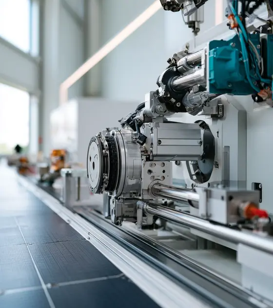
In short:Space mechanisms run slowly, in vacuum, across wide temperature swings, for 12–15 years without maintenance, so lubrication, outgassing and torque margin decide the design more than speed or power. Size the drive to the ECSS or NASA motorisation rule, choose materials that pass ASTM E595 outgassing limits, and qualify the whole mechanism; ground support and test equipment can use carefully prepared industrial parts.
Typical requirements
| Solar array drive power transfer (published examples) | 8–9 kW to about 22 kW through the slip ring |
|---|---|
| Solar array drive output step and speed | 0.005–0.0074° per full step, about 1°/s maximum |
| Design life (published examples) | 12–15 years; qualified to 125,000–133,000 output revolutions |
| Operating temperature (spacecraft side, examples) | About -30 to +70 °C operational, -40 to +90 °C survival |
| Torque margin rule (ECSS-E-ST-33-01C) | Twice the sum of resistive torques, each with its own uncertainty factor (friction ×3 if theoretical) |
| Outgassing screening (ASTM E595) | TML ≤ 1.0%, CVCM ≤ 0.10% after 24 h at 125 °C in vacuum |
| Vacuum-prepared stage bake-out (example) | 85 °C for 8 h at 10⁻⁷ torr |
Machinery we specify motion for
- Satellite solar array drive mechanisms
- Antenna pointing mechanisms
- Planetary rover wheel and arm drives
- Launcher actuation and fuel-control valves
- Spacecraft and test hexapods
- Space telescope focus and pointing mechanisms
- Vacuum and cryogenic mechanisms
- Thermal-vacuum chamber test fixtures
- Ground station antenna positioners
What makes space mechanisms different
A space mechanism moves slowly and rarely by industrial standards, but it has to work every time for well over a decade with no maintenance, after surviving launch vibration, in hard vacuum and through repeated hot and cold cycles. Published solar array drives make the point: Kongsberg’s KARMA-5 TG is specified for 15 years and qualified to 125,000 output revolutions, and Beyond Gravity’s SEPTA42 for 12 years with qualification runs of more than 133,000 full revolutions on its S variants. Both turn at about 1°/s at most.
Three things follow. Lubrication and materials matter more than raw performance. Torque margin is set by rule, not by judgement. And the whole mechanism is qualified as a unit, so component choices are fixed early.
Where motion components sit in space hardware
| Mechanism | Typical drive train | Key components |
|---|---|---|
| Solar array drive (SADM) | Redundant stepper, gearbox, slip ring | Stepper, gear, power and signal slip ring, position sensor |
| Antenna pointing mechanism | Stepper or brushless motor, gear, two axes | Motor, strain-wave or planetary gear, encoder, RF rotary joint or cable wrap |
| Rover wheel and arm | Brushless motor with high-ratio gear | Motor, strain-wave gear, brake, encoder |
| Launcher actuation and valves | Electromechanical or electrohydraulic actuator | Motor, screw, gear, position sensor |
| Hexapod | Six linear legs | Fine-lead screw actuators, motors, encoders |
| Telescope and instrument mechanisms | Stepper, piezo or direct drive | Fine positioning motors, encoders |
| Ground test fixtures | Industrial axes adapted for vacuum or cold | Steppers, linear motors, slip rings, drives |
Harmonic Drive lists satellite solar panel orientation, rovers and launcher fuel-control systems among its space uses, with launcher valves operating down to -60 °C in vacuum. Moog lists six-axis hexapods alongside spacecraft mechanisms and launcher actuation.
How to size a space mechanism: torque margin
Space programmes size drives against a defined rule. As quoted in a NASA conference paper by Moog, Astrium and MDA engineers, ECSS-E-ST-33-01C sets the minimum actuation torque as:
T_min = 2 × (1.1 I + 1.2 S + 1.5 HM + 3 FR + 3 HY + 3 HA + 3 HD) + 1.25 TD + TL
where I is inertial torque, S spring torque, HM motor magnetic losses, FR friction, HY hysteresis, HA harness drag and HD adhesion. TD is the inertial resistance from the worst-case acceleration the customer specifies, and TL is any deliverable output torque the customer specifies. The factors for friction, hysteresis and harness drop from 3 to 1.5, and magnetic losses from 1.5 to 1.2, once they are measured rather than estimated. NASA-STD-5017 instead requires an operating torque margin of at least 1.0 when test-verified.
Worked example
A rotary mechanism has these worst-case resistive torques at the output: inertia 0.05 Nm, motor magnetic losses 0.1 Nm, bearing friction 0.4 Nm and harness drag 0.3 Nm, all estimated, with no spring or hysteresis.
- Estimated values: 2 × (1.1 × 0.05 + 1.5 × 0.1 + 3 × 0.4 + 3 × 0.3) = 2 × 2.31 = 4.6 Nm.
- Measured values: after tests on an engineering model, 2 × (1.1 × 0.05 + 1.2 × 0.1 + 1.5 × 0.4 + 1.5 × 0.3) = 2 × 1.23 = 2.5 Nm.
- Motor: with a 1:36 gear at an assumed 70% efficiency, the motor must deliver 4.6 / (36 × 0.7) = 0.18 Nm on estimated values, or 0.10 Nm once measured, at the coldest temperature, lowest voltage and end of life.
- Speed: a sun-tracking array in low Earth orbit turns once per orbit, about 360° in 95 minutes, or 0.06°/s, well inside a 1°/s drive.
Measuring friction and harness drag early can almost halve the motor, which saves mass and power. Harness drag counts: SEPTA42’s unpowered holding torque varies from 1.4 to 2.4 Nm with position because of its cable wrap.
Vacuum, outgassing and lubrication
Outgassing. Materials are screened to ASTM E595: a sample is held at 125 °C for 24 hours in vacuum, and NASA Goddard’s outgassing database lists materials with total mass loss of no more than 1.0% and collected volatile condensable material of no more than 0.10%. Insulation, potting, adhesives, cable sheaths and grease all count.
Lubrication. Harmonic Drive uses dry-lubricated ZirconLine actuators on satellites. Vacuum stages on the ground typically use perfluoropolyether oils; Dover Motion quotes a vapour pressure of 9 × 10⁻⁹ torr at 100 °C for its choice, with motors built from 220 °C magnet wire and PTFE-insulated leads, then baked at 85 °C for 8 hours at 10⁻⁷ torr.
Heat. With no convection, motors shed heat only by conduction and radiation. Dover recommends drives that cut phase current when the axis is idle. Lin Engineering, for its vacuum-rated motors, reports 0.008% total mass loss in its own 72-hour test at 125 °C. Treat such figures as supplier data and check them against your contamination budget.
Surfaces. Ordinary anodising traps water vapour and creates a virtual leak that can take days to pump away, so vacuum hardware often uses electroless nickel plating instead.
Launch loads, temperature and redundancy
A mechanism must survive launch before it ever moves. Kongsberg qualifies KARMA-5 TG to 1,800 N axial and 2,000 N radial load and a 300 Nm cross-axis moment, and gives operating limits of -30 to +75 °C with non-operating limits of -50 to +85 °C. Beyond Gravity’s SEPTA42 shows how different the two ends of one mechanism can be: on the spacecraft side it is qualified from -40 °C cold start to +90 °C hot survival, but on the solar array side from -70 °C to +110 °C.
Redundancy is designed in rather than added. KARMA-5 TG uses a redundant two-phase bipolar stepper and redundant potentiometers with ±0.05% full-scale linearity; SEPTA42 uses redundant reference switches. For a component specifier, that means asking early for dual windings, dual sensor tracks and segregated harness routes, because they change the motor, encoder and slip ring designs.
Slip rings, encoders and gears
The slip ring of a solar array drive carries all of the array’s power: KARMA-5 TG modules carry 18 power tracks at 8.85 A each, up to 8–9 kW, and SEPTA42 variants reach about 22 kW at a 150 V line. Position feedback on these units comes from redundant potentiometers or reference switches, while pointing mechanisms use encoders for absolute angle. For gearing, read harmonic vs planetary vs cycloidal; for slip ring basics, how to specify a slip ring.
Ground support and test equipment
Most motion hardware a space company buys never flies. It goes into thermal-vacuum chamber fixtures, hexapods for optical alignment, deployment test rigs, spin and balance machines and ground station antennas. Here industrial components work well when you prepare them for the environment: vacuum-compatible linear motors such as the Akribis AWM, wide-temperature encoders such as the Netzer VLT (-55 to +125 °C), and slip rings with vacuum sealing or wide temperature ranges such as the High & Low Temperature Slip Ring. Our page on satellite and antenna systems covers ground positioners.
Typical pitfalls
- Sizing for nominal friction instead of applying the programme’s uncertainty factors at cold, end-of-life conditions.
- Ignoring harness and cable-wrap drag, which can be a large share of the resistive torque.
- Missing outgassing on small parts: cable ties, connector inserts and encoder adhesives.
- Overheating motors in vacuum by leaving full holding current on.
- Treating a catalogue part as flight-ready. Engineering models and ground equipment can use it; flight hardware needs a qualification plan.
Tell us whether the hardware flies, its loads, life, temperature and vacuum requirements, and our specialist engineering and supply partners can propose suitable motors, gears, encoders and slip rings, or flag where a custom build is needed.
Strain-wave gears for space mechanisms and cryogenic use
Strain-wave gears give high ratios with zero backlash in one light stage, which is why they appear in solar array drives, rover wheels and pointing mechanisms. For flight, the gear set, lubricant and materials are qualified together: dry lubrication or space-grade perfluoropolyether greases, controlled outgassing and tested cold-start torque. Specify ratio, repeated peak and momentary torque, stiffness, the full temperature range including survival, vacuum level, life in output revolutions and the torque margin rule your programme uses. Flat and hollow-shaft component sets suit engineering models, ground support equipment and test fixtures; flight builds need a qualification plan agreed with the supplier.
- Solar array drives: high-ratio, low-speed rotation
- Rover wheel and arm joints: compact zero-backlash reduction
- Antenna pointing: precise two-axis positioning
- Test fixtures: rotary positioning inside thermal-vacuum chambers
Available through our supply network
All gearboxes and harmonic drives →Specify gearboxes and harmonic drives for space →
Slip rings for satellite mechanisms and space test rigs
A solar array drive passes all the array's power through its slip ring, from a few kilowatts to over 20 kW on large spacecraft, while signal rings carry telemetry and position data. Flight rings use precious-metal contacts, controlled wear debris and materials that pass outgassing screening. Specify power and signal circuits, current per track, line voltage, speed, life in revolutions, vacuum and temperature range, and redundancy. On the ground, slip rings carry power and instrumentation onto rotating test fixtures, ground station antennas and thermal-vacuum turntables, where catalogue designs with vacuum sealing or wide temperature ranges can work.
- Solar array drives: array power and telemetry across rotation
- Thermal-vacuum turntables: power and sensor lines to the test article
- Ground station antennas: power, data and RF through the azimuth axis
- Spin and balance rigs: instrumentation at speed
Available through our supply network
Space rated encoders and position sensors for pointing mechanisms
Pointing mechanisms and hexapods need absolute angle feedback that survives temperature cycling, vacuum and radiation, with low mass and power. Many flight solar array drives use redundant potentiometers or reference switches; pointing mechanisms and instruments use optical, inductive or capacitive encoders. Specify resolution and accuracy over the operating range, temperature limits, power, interface, radiation tolerance and outgassing data. Contactless capacitive and inductive encoders with -55 °C or -60 °C lower limits suit cold test, ground equipment and engineering models; radiation-tolerant electronics are a separate qualification question.
- Antenna and instrument pointing: absolute axis angle
- Hexapods: leg or joint position
- Thermal-vacuum fixtures: rotary position at temperature
- Ground station positioners: azimuth and elevation
Available through our supply network
All encoders and feedback →Specify encoders and feedback for space →
Stepper motors for space mechanisms and vacuum test equipment
Stepper motors dominate slow space mechanisms because they hold position unpowered, move in known increments without feedback and can be wound redundantly; published solar array drives use two-phase steppers with output steps of thousandths of a degree. In vacuum there is no convection, so the motor must shed heat by conduction, and standard insulation, lubricants and adhesives can outgas. Specify holding and detent torque, step angle, winding redundancy, insulation class, bearing lubricant, vacuum level and bake-out temperature. Catalogue hybrid steppers suit breadboards and atmospheric ground equipment; vacuum preparation is a special build to agree with the supplier.
- Solar array and antenna drives: stepped low-speed rotation
- Instrument mechanisms: filter wheels and focus stages
- Vacuum chamber stages: positioning test articles
Available through our supply network
All servo and stepper motors →Specify servo and stepper motors for space →
Frameless torque motors for space pointing and gimbals
Frameless brushless motors build directly into the mechanism housing, avoid a second bearing set and leave a large bore for harness or optics. Direct drive removes gear backlash and wear, which helps fine pointing and smooth scanning, at the price of more motor mass for a given torque. Specify continuous torque at the coldest and hottest conditions, cogging and torque ripple, bus voltage, thermal path in vacuum and the magnet and insulation materials. Low-voltage kits suit test gimbals, star tracker test stands and ground antenna positioners.
- Instrument and antenna pointing: direct-drive axes
- Ground test gimbals: smooth low-speed rotation
- Ground station positioners: direct-drive azimuth
Available through our supply network
All frameless and torque motors →Specify frameless and torque motors for space →
Precision actuators for hexapods and vacuum stages
Hexapods position mirrors, instruments and test articles in six degrees of freedom through six extendable legs, each a precision actuator with a fine-lead screw, motor and feedback. Vacuum stages for optics and detector testing use ironless linear motors, piezo motors or vacuum-prepared screw actuators. Specify stroke, resolution and repeatability, load, stiffness, holding behaviour when unpowered, vacuum level and outgassing limits. Self-braking piezo motors hold position with power off, which helps in thermal-vacuum tests where motor heat must be kept to a minimum.
- Test hexapods: align mirrors and instruments
- Vacuum optical benches: fine linear positioning
- Thermal-vacuum chambers: move test articles without opening the chamber
Available through our supply network
Servo and stepper drives for space test and ground equipment
Flight mechanism drive electronics are usually part of the spacecraft avionics, built from radiation-tolerant parts. Ground support equipment, hexapods and test stands use commercial drives, chosen for low noise, fine current resolution and a feedback interface that matches the encoder. Specify supply voltage, current, feedback type, fieldbus, cable length into the chamber and EMC needs near sensitive instruments. Small board-level drives can sit outside the chamber with long, filtered leads. Choose drives that can reduce current at standstill, since motor heat inside a vacuum chamber is hard to remove and can disturb thermal measurements.
- Hexapods: six coordinated leg drives
- Thermal-vacuum fixtures: motors driven through chamber feedthroughs
- Ground antennas: azimuth and elevation drives
Available through our supply network
Standards to have in view
- ECSS-E-ST-33-01C (space engineering: mechanisms; check the current revision)
- NASA-STD-5017 (design and development requirements for mechanisms)
- ASTM E595 (total mass loss and collected volatile condensable materials from outgassing in a vacuum)
- ECSS-Q-ST-70-02C (thermal vacuum outgassing test for the screening of space materials)
- ECSS-E-ST-10-03C (space engineering: testing)
- EN 9100 / AS9100 (quality management for aviation, space and defence organisations)
Which standards apply depends on the end product and its market. Your engineer will confirm what the component itself needs to meet.
Frequently asked questions
What torque margin does a space mechanism need?
Under ECSS-E-ST-33-01C the minimum actuation torque is twice the sum of the resistive torques, each multiplied by an uncertainty factor: 1.1 for inertia, 1.2 for springs, 1.5 for motor magnetic losses, 3 for friction, hysteresis and harness drag if estimated (1.5 if measured), and 3 for adhesion. NASA-STD-5017 requires an operating torque margin of at least 1.0 when test-verified. Check which rule your programme applies.
Can I use a standard stepper motor in vacuum?
Not as it comes. Standard insulation, adhesives and greases outgas, and with no air the windings run hotter. Vacuum-prepared motors use high-temperature magnet wire, PTFE-insulated leads, vacuum-compatible bearing lubricant and a bake-out; Dover Motion's vacuum stages, for example, bake motors at 85 °C for 8 hours at 10⁻⁷ torr. Reduce idle current to keep heat down.
What are the ASTM E595 outgassing limits?
The common screening limits are total mass loss (TML) of no more than 1.0% and collected volatile condensable material (CVCM) of no more than 0.10%. The test holds a sample at 125 °C for 24 hours in vacuum, with a collector plate at 25 °C, as described in NASA Goddard's outgassing database guide. Passing screening does not replace a contamination analysis for sensitive optics.
How much power does a solar array drive slip ring carry?
It depends on the spacecraft. Kongsberg publishes its KARMA-5 TG at 8–9 kW with up to four slip ring modules, each with 18 power tracks at 8.85 A. Beyond Gravity publishes SEPTA42 variants from under 7.8 kW to about 22 kW at a 150 V line. Both use stepper drive trains and run at about 1°/s maximum.
Why use strain-wave gears in space?
They give a high ratio with zero backlash in one compact, light stage, and work with dry lubrication. Harmonic Drive states that its gears flew on the Apollo missions and served as wheel drives on the Spirit and Opportunity Mars rovers, and that special versions operate down to -268 °C. The gear, lubricant and materials still need qualifying for each mission.
What should I send for a space mechanism enquiry?
Say whether the part is flight hardware, an engineering model or ground and test equipment. Send loads, speeds and travel, required life in revolutions or cycles, temperature range (operating and survival), vacuum level, outgassing limits, radiation environment, mass and power budget, redundancy needs, the torque margin rule you work to, and documentation and quality requirements.
Sources
- Harmonic Drive: Aviation and space
- Moog: Space
- NASA NTRS: A recommended new approach on motorization ratio calculations of stepper motors (Nalbandian, Blais, Horth)
- Kongsberg: KARMA-5 TG solar array drive product data sheet
- Beyond Gravity: SEPTA42 solar array drive mechanism datasheet
- NASA Goddard: Outgassing database user guide
- Dover Motion: High vacuum positioning tables
- Lin Engineering: Vacuum rated motors
Figures are summarised from the sources above and from manufacturers' published data on the date shown. Always confirm against the current datasheet for your exact part.